Step | Task (continued) |
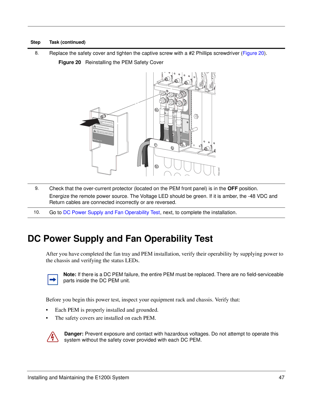
8.Replace the safety cover and tighten the captive screw with a #2 Phillips screwdriver (Figure 20). Figure 20 Reinstalling the PEM Safety Cover
fn00108lp |
9.Check that the
Energize the remote power source. The Voltage LED should be green. If it is amber, the
10.Go to DC Power Supply and Fan Operability Test, next, to complete the installation.
DC Power Supply and Fan Operability Test
After you have completed the fan tray and PEM installation, verify their operability by supplying power to the chassis and verifying the status LEDs.
Note: If there is a DC PEM failure, the entire PEM must be replaced. There are no
Before you begin this power test, inspect your equipment rack and chassis. Verify that:
•Each PEM is properly installed and grounded.
•The safety covers are installed on each PEM.
Danger: Prevent exposure and contact with hazardous voltages. Do not attempt to operate this system without the safety cover provided with each DC PEM.
Installing and Maintaining the E1200i System | 47 |