Chapter 5: Advanced Serverboard Setup
Power LED/Speaker
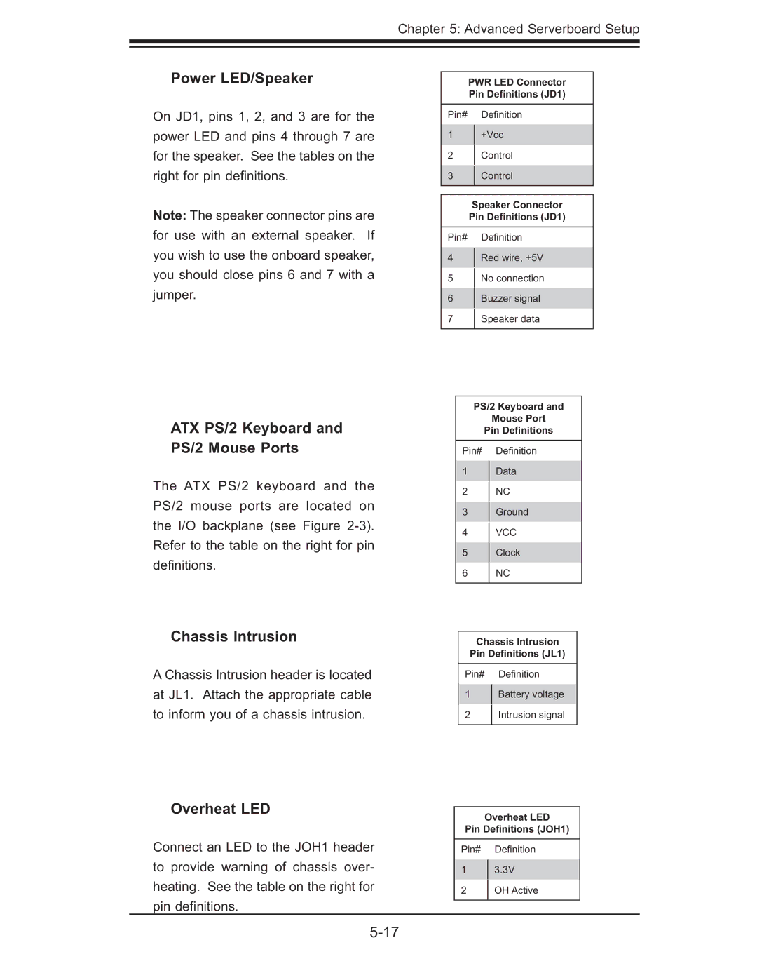
On JD1, pins 1, 2, and 3 are for the power LED and pins 4 through 7 are for the speaker. See the tables on the right for pin defi nitions.
Note: The speaker connector pins are for use with an external speaker. If you wish to use the onboard speaker, you should close pins 6 and 7 with a jumper.
ATX PS/2 Keyboard and PS/2 Mouse Ports
The ATX PS/2 keyboard and the PS/2 mouse ports are located on the I/O backplane (see Figure
Chassis Intrusion
A Chassis Intrusion header is located at JL1. Attach the appropriate cable to inform you of a chassis intrusion.
Overheat LED
Connect an LED to the JOH1 header to provide warning of chassis over- heating. See the table on the right for pin defi nitions.
PWR LED Connector Pin Definitions (JD1)
Pin# Defi nition
1+Vcc
2Control
3Control
Speaker Connector Pin Definitions (JD1)
Pin# Defi nition
4Red wire, +5V
5 No connection
6Buzzer signal
7 Speaker data
PS/2 Keyboard and
Mouse Port
Pin Definitions
Pin# Defi nition
1Data
2NC
3Ground
4VCC
5Clock
6 NC
Chassis Intrusion
Pin Definitions (JL1)
Pin# Defi nition
1Battery voltage
2Intrusion signal
Overheat LED
Pin Definitions (JOH1)
Pin# Defi nition
13.3V
2OH Active