Chapter 5: Advanced Serverboard Setup
5-8 Connecting Cables
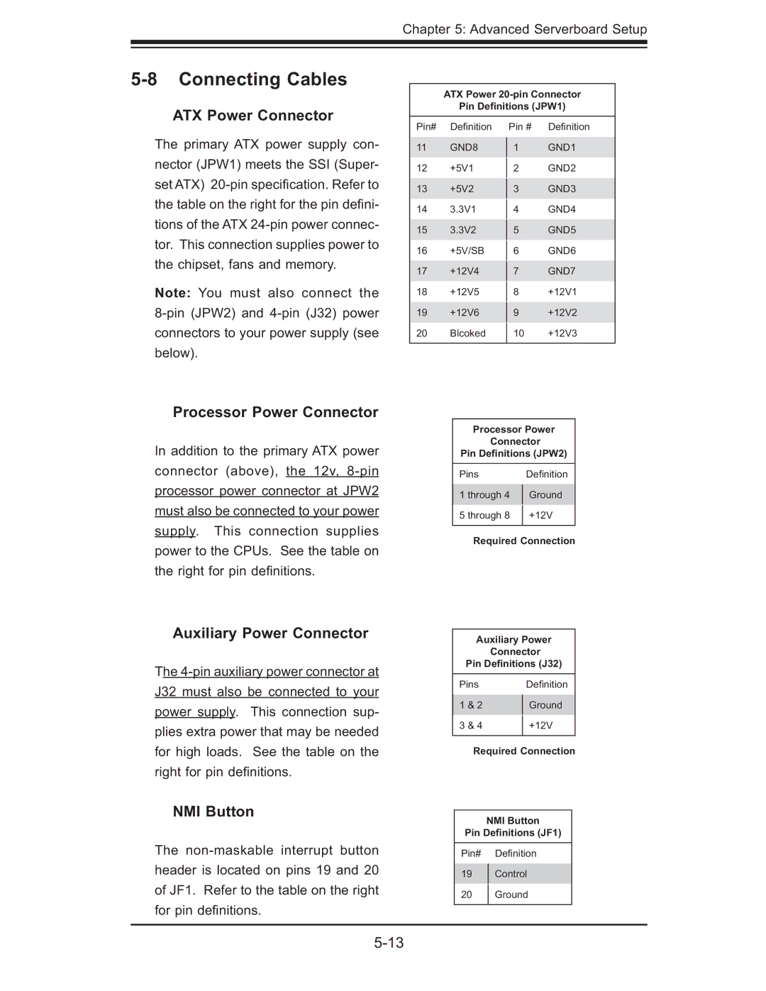
ATX Power Connector
The primary ATX power supply con- nector (JPW1) meets the SSI (Super- set ATX)
Note: You must also connect the
ATX Power 20-pin Connector
Pin Definitions (JPW1)
Pin# | Defi nition | Pin # | Defi nition | |
11 | GND8 | 1 | GND1 | |
12 | +5V1 |
| GND2 | |
2 | ||||
13 | +5V2 |
| GND3 | |
3 | ||||
14 | 3.3V1 |
| GND4 | |
4 | ||||
15 | 3.3V2 |
| GND5 | |
5 | ||||
16 | +5V/SB |
| GND6 | |
6 | ||||
17 | +12V4 |
| GND7 | |
7 | ||||
18 | +12V5 |
| +12V1 | |
8 | ||||
19 | +12V6 |
| +12V2 | |
9 | ||||
20 | Blcoked | 10 | +12V3 | |
|
|
|
|
Processor Power Connector
In addition to the primary ATX power connector (above), the 12v,
Auxiliary Power Connector
The
NMI Button
The
Processor Power
Connector
Pin Definitions (JPW2)
Pins | Defi nition | |
1 through 4 | Ground | |
5 through 8 | +12V | |
|
|
Required Connection
Auxiliary Power
Connector
Pin Definitions (J32)
Pins | Defi nition | |
1 & 2 | Ground | |
3 & 4 | +12V | |
|
|
Required Connection
NMI Button
Pin Definitions (JF1)
Pin# Defi nition
19Control
20Ground