Power Fail Header
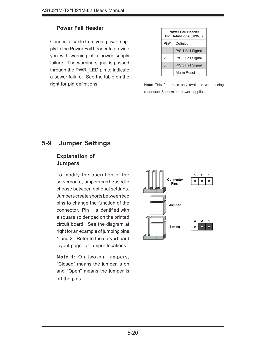
Connect a cable from your power sup- ply to the Power Fail header to provide you with warning of a power supply failure. The warning signal is passed through the PWR_LED pin to indicate a power failure. See the table on the right for pin defi nitions.
Power Fail Header
Pin Definitions (JPWF)
Pin# Defi nition
1P/S 1 Fail Signal
2 P/S 2 Fail Signal
3 P/S 3 Fail Signal
4Alarm Reset
Note: This feature is only available when using redundant Supermicro power supplies.
5-9 Jumper Settings
Explanation of
Jumpers
To modify the operation of the serverboard,jumperscanbeusedto choose between optional settings. Jumpers create shorts between two pins to change the function of the connector. Pin 1 is identifi ed with a square solder pad on the printed circuit board. See the diagram at right for an example of jumping pins 1 and 2. Refer to the serverboard layout page for jumper locations.
Note 1: On
3 2 1
Connector
Pins
Jumper
3 2 1
Setting