Chapter 5: Advanced Serverboard Setup
Power Fail LED
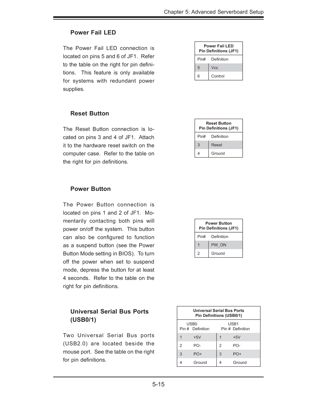
The Power Fail LED connection is located on pins 5 and 6 of JF1. Refer to the table on the right for pin defi ni- tions. This feature is only available for systems with redundant power supplies.
Reset Button
The Reset Button connection is lo- cated on pins 3 and 4 of JF1. Attach it to the hardware reset switch on the computer case. Refer to the table on the right for pin defi nitions.
Power Fail LED
Pin Definitions (JF1)
Pin# Defi nition
5Vcc
6Control
Reset Button
Pin Definitions (JF1)
Pin# Defi nition
3Reset
4 Ground
Power Button
The Power Button connection is located on pins 1 and 2 of JF1. Mo- mentarily contacting both pins will power on/off the system. This button can also be confi gured to function as a suspend button (see the Power Button Mode setting in BIOS). To turn off the power when set to suspend mode, depress the button for at least 4 seconds. Refer to the table on the right for pin defi nitions.
Universal Serial Bus Ports (USB0/1)
Power Button
Pin Definitions (JF1)
Pin# Defi nition
1PW_ON
2 Ground
Universal Serial Bus Ports Pin Definitions (USB0/1)
Two Universal Serial Bus ports (USB2.0) are located beside the mouse port. See the table on the right for pin defi nitions.
USB0
Pin # Defi nition
1+5V
2PO-
3PO+
4Ground
USB1
Pin # Defi nition
1+5V
2PO-
3PO+
4Ground