![]()
![]()
![]()
![]() C2SEA/C2SEE User’s Manual
C2SEA/C2SEE User’s Manual
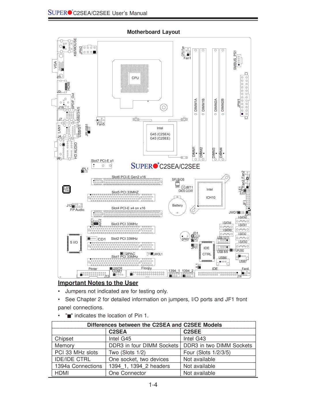
Motherboard Layout
KB/MOUSE | JPW2 | CPU Fan |
Fan1
VGA
SMBUS_PS1![]()
![]()
J17
CPU
J3 | HDMI |
|
_Out |
| |
| USB2/3/4/5 | |
J18 | SPDIF | |
|
| |
J7 |
|
|
LAN1 |
| USB/0/1 |
J4 |
|
|
J6 |
| HD AUDIO |
|
|
JPUSB1![]()
Fan5
Slot7
Intel |
G45 (C2SEA) |
G43 (C2SEE) |
DIMM1A
DIMM1
DIMM1B
DIMM2
DIMM2A
DIMM3
DIMM2B
DIMM4
JPW1![]()
JPL1


 C2SEA/C2SEE
![]() Lan
Lan![]()
CTRL
J12![]()
![]()
![]()
![]()
![]()
![]()
![]()
![]() FP Audio
FP Audio
Slot6
Slot5 PCI 33MHZ
Slot4
SPI BIOS
![]() JBT1
JBT1
CMOS CLEAR
Battery
Intel |
ICH10 |
LE1 | Fan3 Fan2 |
JLED1 | |
| JF1 |
JI2C1 | JI2C2 |
Slot3 PCI 33MHz
JWD1 |
JOH1 |
CD1 | Slot2 PCI 33MHz |
|
S I/O |
|
|
| JPAC | JWOL1 |
| Slot1 PCI 33MHz |
|
Printer | JWOR | Floopy |
| COM1 |
|
J13 |
|
|
JD1 | USB 10/11 | ||
SPKR1 JPD1 | |||
|
| ||
JPI1 | IDE | JPUSB2 | |
| USB 8/9 | ||
| CTRL |
| |
| USB6 | USB7 | |
JL1 |
| ||
IDE | Fan4 | ||
1394_1 1394_2 | |||
|
| ||
|
| J14 |
Important Notes to the User
•Jumpers not indicated are for testing only.
•See Chapter 2 for detailed information on jumpers, I/O ports and JF1 front panel connections.
•"![]() " indicates the location of Pin 1.
" indicates the location of Pin 1.
Differences between the C2SEA and C2SEE Models
|
| C2SEA | C2SEE |
|
| Chipset | Intel G45 | Intel G43 |
|
| Memory | DDR3 in four DIMM Sockets | DDR3 in two DIMM Sockets |
|
| PCI 33 MHz slots | Two (Slots 1/2) | Four (Slots 1/2/3/5) |
|
| IDE/IDE CTRL | One socket, two devices | Not available |
|
| 1394a Connections | 1394_1, 1394_2 headers | Not available |
|
| HDMI | One Connector | Not available |
|
|
|
|
|
|