Chapter 2: Installation
2-9 Parallel Port Connector and IDE Hard Drive Connections
Note the following when connecting the hard disk drive cables:
• A red mark on a wire typically designates the location of pin 1.
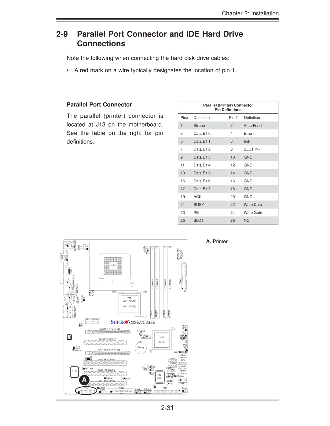
Parallel Port Connector
Parallel (Printer) Connector
Pin Definitions
The parallel (printer) connector is located at J13 on the motherboard. See the table on the right for pin definitions.
Pin# Definition
1Strobe-
3Data Bit 0
5Data Bit 1
7Data Bit 2
9Data Bit 3
11Data Bit 4
13Data Bit 5
15Data Bit 6
17Data Bit 7
19ACK
21BUSY
23PE
25SLCT
Pin # Definition
2 Auto Feed-
4 Error-
6 Init-
8SLCT IN-
10GND
12GND
14GND
16GND
18GND
20GND
22Write Data
24Write Gate
26NC
KB/MOUSE JPW2 | CPU Fan |
| Fan1 |
VGA
HDMI |
|
SPDIF Out | USB2/3/4/5 |
LAN1 | USB/0/1 |
HD AUDIO | |
CPU
JPUSB1 | Fan5 |
G45 (C2SEA) | |
| Intel |
| G43 (C2SEE) |
| Slot7 |
DIMM1A | DIMM1B |
DIMM1 | DIMM2 |
DIMM2A | DIMM2B |
DIMM3 | DIMM4 |
JPL1 |
| C2SEA/C2SEE |
| |
| Slot6 | SPI BIOS |
| |
|
|
| ||
Lan |
| JBT1 | Intel | |
CTRL | Slot5 PCI 33MHZ | CMOS CLEAR | ||
| ||||
|
| ICH10 | ||
|
|
| ||
|
| Battery |
|
JPW1
SMBUS_PS1
Fan2Fan3![]()
LE1![]()
![]()
![]()
![]()
JLED1![]()
JF1![]()
![]()
A.Printer
FP Audio |
| Slot4 | |
JI2C1 | JI2C2 | Slot3 PCI 33MHz |
|
S I/O | CD1 | Slot2 PCI 33MHz |
|
|
| ||
|
|
| |
A |
| JPAC | JWOL1 |
|
| Slot1 PCI 33MHz |
|
Printer |
| JWOR | Floopy |
|
| COM1 |
|
|
| JWD1 | JOH1 | |
|
|
|
| |
|
|
|
| |
|
|
| ||
|
|
|
| |
JD1 |
|
| ||
| USB 10/11 |
| ||
SPKR1 JPD1 |
|
| ||
|
|
|
| |
JPI1 | IDE | USB 8/9 | JPUSB2 | |
| CTRL | |||
|
|
| ||
| USB6 |
|
| |
|
|
| USB7 | |
JL1 |
|
|
| |
| IDE |
| Fan4 | |
1394_1 1394_2 |
|
| ||
|
|
|
| |