Chapter 2: Installation
2-7 Jumper Settings
Explanation of
Jumpers
To modify the operation of the motherboard, jumpers can be used to choose between optional settings. Jumpers create shorts
Connector
Pins
Jumper
Cap
3 2 1
between two pins to change the function of the connector. Pin 1 is identified with a square solder pad on the printed circuit board. See the motherboard layout pages for jumper locations.
Note: On two pin jumpers, "Closed" means the jumper is on and "Open" means the jumper is off the pins.
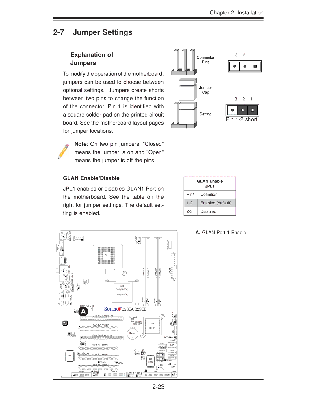
GLAN Enable/Disable
JPL1 enables or disables GLAN1 Port on the motherboard. See the table on the right for jumper settings. The default set- ting is enabled.
3 2 1
Setting
Pin 1-2 short
GLAN Enable
JPL1
Pin# |
| Definition |
| Enabled (default) | |
| ||
| Disabled | |
| ||
|
|
|
KB/MOUSE JPW2 | CPU Fan |
| Fan1 |
VGA
HDMI |
|
SPDIF Out | USB2/3/4/5 |
LAN1 | USB/0/1 |
HD AUDIO | |
CPU
JPUSB1 | Fan5 |
G45 (C2SEA) | |
| Intel |
| G43 (C2SEE) |
| Slot7 |
DIMM1A | DIMM1B |
DIMM1 | DIMM2 |
DIMM2A | DIMM2B |
DIMM3 | DIMM4 |
JPL1 A | Slot6 | C2SEA/C2SEE |
| |
| SPI BIOS |
| ||
|
|
| ||
Lan |
| JBT1 | Intel | |
CTRL | Slot5 PCI 33MHZ | CMOS CLEAR | ||
| ||||
|
| ICH10 | ||
|
|
| ||
|
| Battery |
|
JPW1
SMBUS_PS1
Fan2Fan3![]()
LE1![]()
![]()
![]()
![]()
JLED1![]()
JF1![]()
![]()
A. GLAN Port 1 Enable
FP Audio |
| Slot4 | |
JI2C1 | JI2C2 | Slot3 PCI 33MHz |
|
S I/O | CD1 | Slot2 PCI 33MHz |
|
|
| ||
|
|
| |
|
| JPAC | JWOL1 |
|
| Slot1 PCI 33MHz |
|
Printer |
| JWOR | Floopy |
|
| COM1 |
|
|
| JWD1 | JOH1 | |
|
|
|
| |
|
|
| ||
|
|
|
| |
JD1 |
|
| ||
| USB 10/11 |
| ||
SPKR1 JPD1 |
|
| ||
|
|
|
| |
JPI1 | IDE | USB 8/9 | JPUSB2 | |
| CTRL | |||
|
|
| ||
| USB6 |
|
| |
|
|
| USB7 | |
JL1 |
|
|
| |
| IDE |
| Fan4 | |
1394_1 1394_2 |
|
| ||
|
|
|
| |