![]()
![]()
![]()
![]() C2SEA/C2SEE User's Manual
C2SEA/C2SEE User's Manual
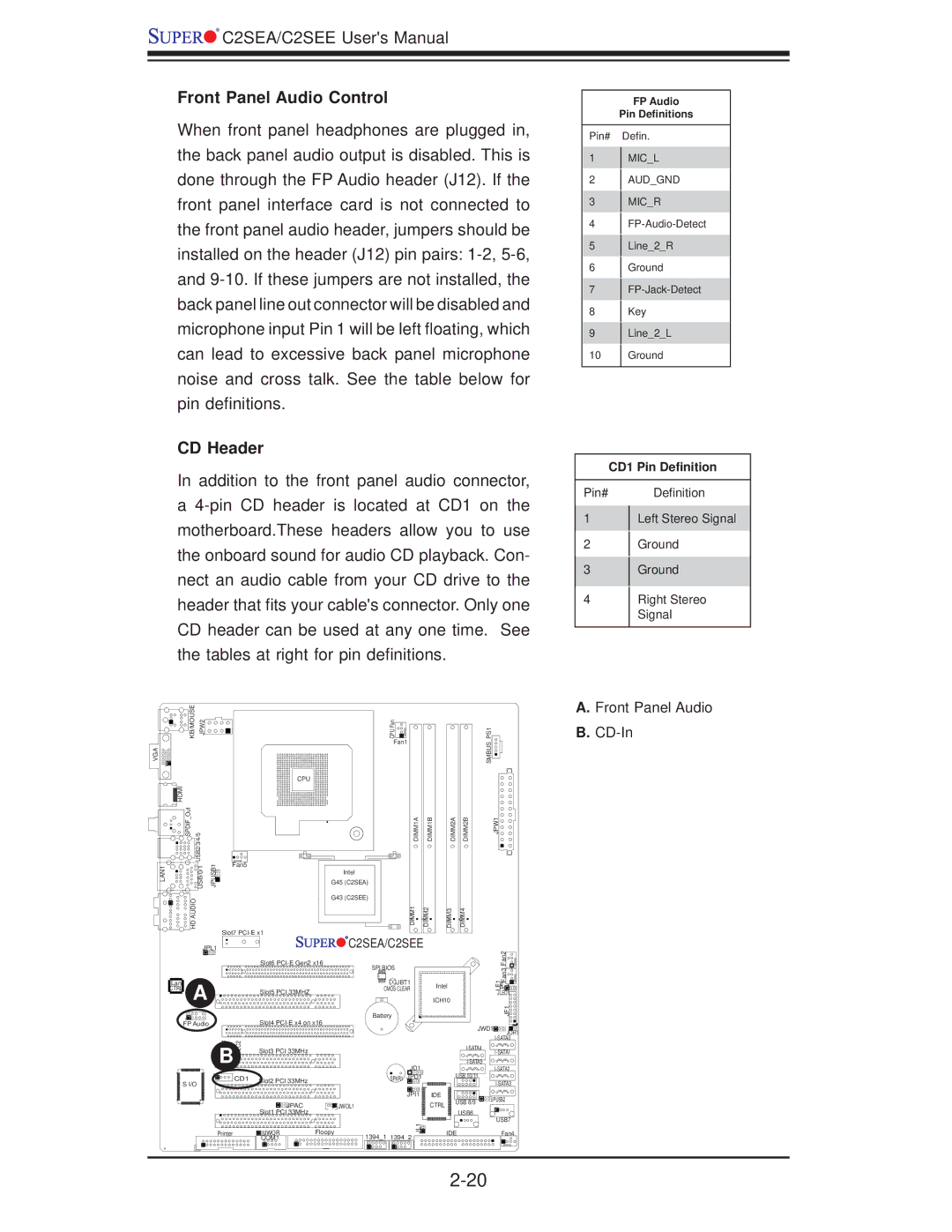
Front Panel Audio Control
When front panel headphones are plugged in, the back panel audio output is disabled. This is done through the FP Audio header (J12). If the front panel interface card is not connected to the front panel audio header, jumpers should be installed on the header (J12) pin pairs:
CD Header
In addition to the front panel audio connector, a
FP Audio
Pin Definitions
Pin# Defin.
1MIC_L
2AUD_GND
3MIC_R
4
5Line_2_R
6Ground
7
8Key
9Line_2_L
10Ground
CD1 Pin Definition
Pin# Definition
1 | Left Stereo Signal | |
2 | Ground | |
3 | Ground | |
4 | Right Stereo | |
| Signal | |
|
|
KB/MOUSE JPW2 | CPU Fan |
| Fan1 |
VGA
HDMI |
|
SPDIF Out | USB2/3/4/5 |
LAN1 | USB/0/1 |
HD AUDIO | |
CPU
JPUSB1 | Fan5 |
G45 (C2SEA) | |
| Intel |
| G43 (C2SEE) |
| Slot7 |
DIMM1A | DIMM1B |
DIMM1 | DIMM2 |
DIMM2A | DIMM2B |
DIMM3 | DIMM4 |
| JPL1 |
| C2SEA/C2SEE |
| |
|
| Slot6 | SPI BIOS |
| |
|
|
|
| ||
Lan | A |
| JBT1 | Intel | |
CTRL | Slot5 PCI 33MHZ | CMOS CLEAR | |||
| |||||
|
| ICH10 | |||
|
|
| |||
|
|
| Battery |
|
JPW1
SMBUS_PS1
Fan2Fan3![]()
LE1![]()
![]()
![]()
![]()
JLED1![]()
JF1![]()
![]()
A. Front Panel Audio |
B. |
FP Audio |
| Slot4 | |
JI2C1 | JI2C2 | Slot3 PCI 33MHz |
|
B |
|
|
|
S I/O | CD1 | Slot2 PCI 33MHz |
|
|
| ||
|
|
| |
|
| JPAC | JWOL1 |
|
| Slot1 PCI 33MHz |
|
Printer |
| JWOR | Floopy |
|
| COM1 |
|
|
| JWD1 | JOH1 | |
|
|
|
| |
|
|
| ||
|
|
|
| |
JD1 |
|
| ||
| USB 10/11 |
| ||
SPKR1 JPD1 |
|
| ||
|
|
|
| |
JPI1 | IDE | USB 8/9 | JPUSB2 | |
| CTRL | |||
|
|
| ||
| USB6 |
|
| |
|
|
| USB7 | |
JL1 |
|
|
| |
| IDE |
| Fan4 | |
1394_1 1394_2 |
|
| ||
|
|
|
| |