Chapter 2: Installation
2-6 Connecting Cables
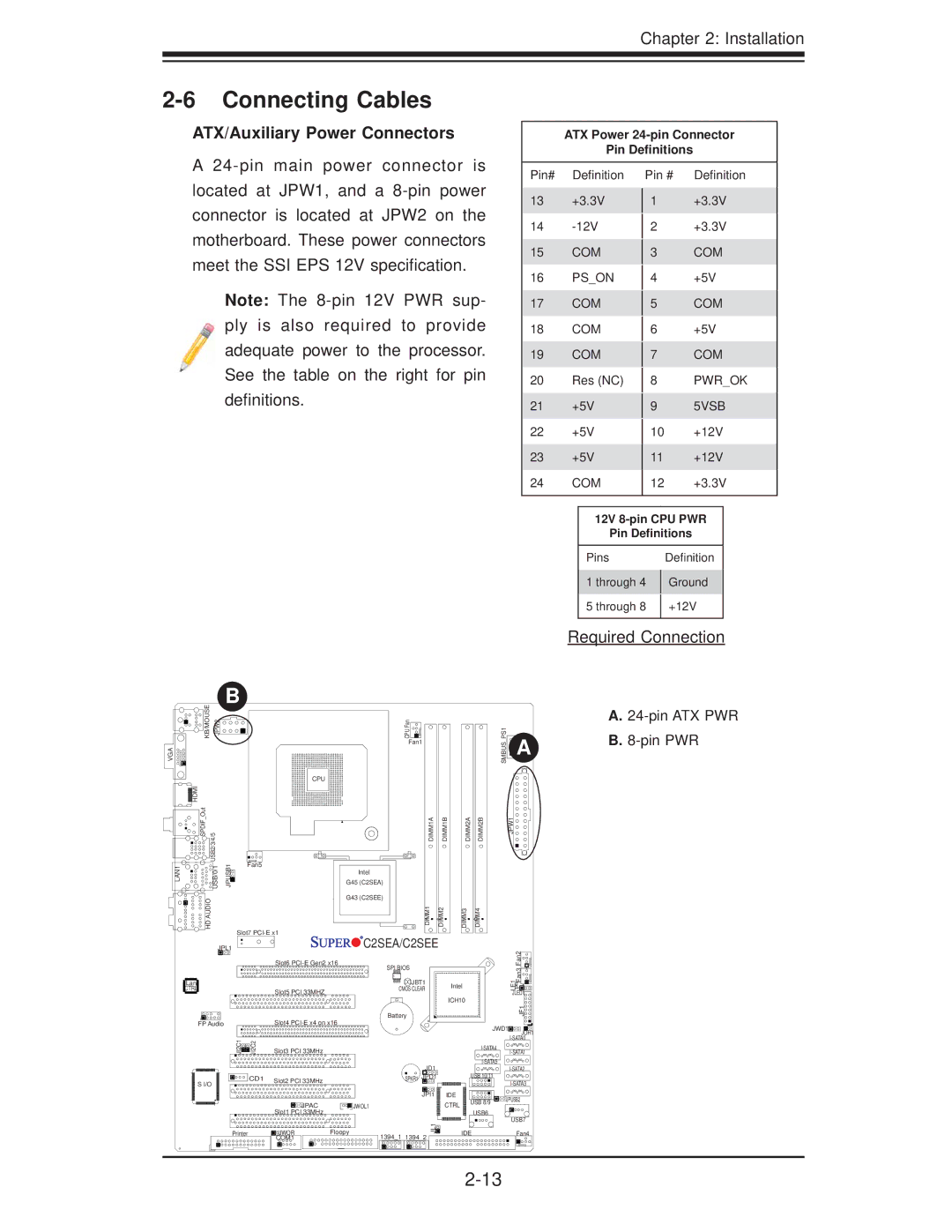
ATX/Auxiliary Power Connectors
ATX Power
Pin Definitions
A
Note: The
Pin# Definition
13+3.3V
14
15COM
16PS_ON
17COM
18COM
19COM
20Res (NC)
21+5V
22+5V
23+5V
24COM
Pin # Definition
1+3.3V
2+3.3V
3COM
4+5V
5COM
6+5V
7COM
8PWR_OK
95VSB
10+12V
11+12V
12+3.3V
12V
Pin Definitions
Pins |
| Definition |
1 through 4 |
| Ground |
| ||
5 through 8 |
| +12V |
| ||
|
|
|
Required Connection
VGA
KB/MOUSE JPW2 | B |
CPU Fan | |
| Fan1 |
HDMI |
|
SPDIF Out | USB2/3/4/5 |
LAN1 | USB/0/1 |
HD AUDIO | |
CPU
JPUSB1 | Fan5 |
G45 (C2SEA) | |
| Intel |
| G43 (C2SEE) |
| Slot7 |
DIMM1A | DIMM1B |
DIMM1 | DIMM2 |
DIMM2A | DIMM2B |
DIMM3 | DIMM4 |
JPL1 |
| C2SEA/C2SEE |
| |
| Slot6 | SPI BIOS |
| |
|
|
| ||
Lan |
| JBT1 | Intel | |
CTRL | Slot5 PCI 33MHZ | CMOS CLEAR | ||
| ||||
|
| ICH10 | ||
|
|
| ||
|
| Battery |
|
SMBUS PS1 | A |
| JPW1 |
Fan2Fan3![]()
LE1![]()
![]()
![]()
![]()
JLED1![]()
JF1![]()
![]()
A.24-pin ATX PWR
B.8-pin PWR
FP Audio |
| Slot4 | |
JI2C1 | JI2C2 | Slot3 PCI 33MHz |
|
S I/O | CD1 | Slot2 PCI 33MHz |
|
|
| ||
|
|
| |
|
| JPAC | JWOL1 |
|
| Slot1 PCI 33MHz |
|
Printer |
| JWOR | Floopy |
|
| COM1 |
|
|
| JWD1 | JOH1 | |
|
|
|
| |
|
|
| ||
|
|
|
| |
JD1 |
|
| ||
| USB 10/11 |
| ||
SPKR1 JPD1 |
|
| ||
|
|
|
| |
JPI1 | IDE | USB 8/9 | JPUSB2 | |
| CTRL | |||
|
|
| ||
| USB6 |
|
| |
|
|
| USB7 | |
JL1 |
|
|
| |
| IDE |
| Fan4 | |
1394_1 1394_2 |
|
| ||
|
|
|
| |