Chapter 2: Installation
Reset Button
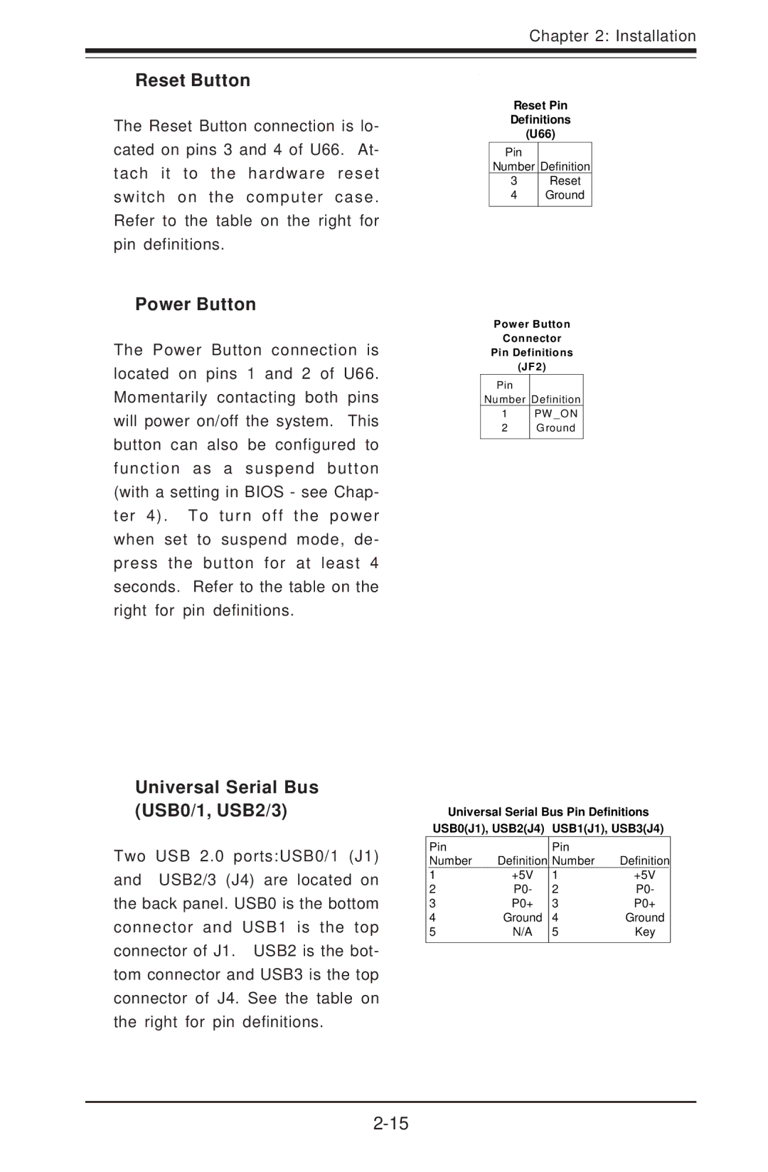
The Reset Button connection is lo- cated on pins 3 and 4 of U66. At- tach it to the hardware reset switch on the computer case. Refer to the table on the right for pin definitions.
Reset Pin
Definitions
(U66)
Pin
Number Definition
3Reset
4Ground
Power Button
The Power Button connection is located on pins 1 and 2 of U66. Momentarily contacting both pins will power on/off the system. This button can also be configured to function as a suspend button (with a setting in BIOS - see Chap- ter 4). To turn off the power when set to suspend mode, de- press the button for at least 4 seconds. Refer to the table on the right for pin definitions.
Power Button
Connector
Pin Definitions
(JF2)
Pin
Number Definition
1PW _O N
2Ground
Universal Serial Bus (USB0/1, USB2/3)
Two USB 2.0 ports:USB0/1 (J1) and USB2/3 (J4) are located on the back panel. USB0 is the bottom connector and USB1 is the top connector of J1. USB2 is the bot- tom connector and USB3 is the top connector of J4. See the table on the right for pin definitions.
Universal Serial Bus Pin Definitions
USB0(J1), USB2(J4) USB1(J1), USB3(J4)
| Pin |
| Pin |
|
|
| Number | Definition | Number | Definition | |
| 1 | +5V | 1 | +5V |
|
2 | P0- | 2 | P0- | ||
3 | P0+ | 3 | P0+ | ||
4 | Ground | 4 | Ground | ||
5 | N/A | 5 | Key | ||
|
|
|
|
|
|