Chapter 2: Installation
Fan Headers
The
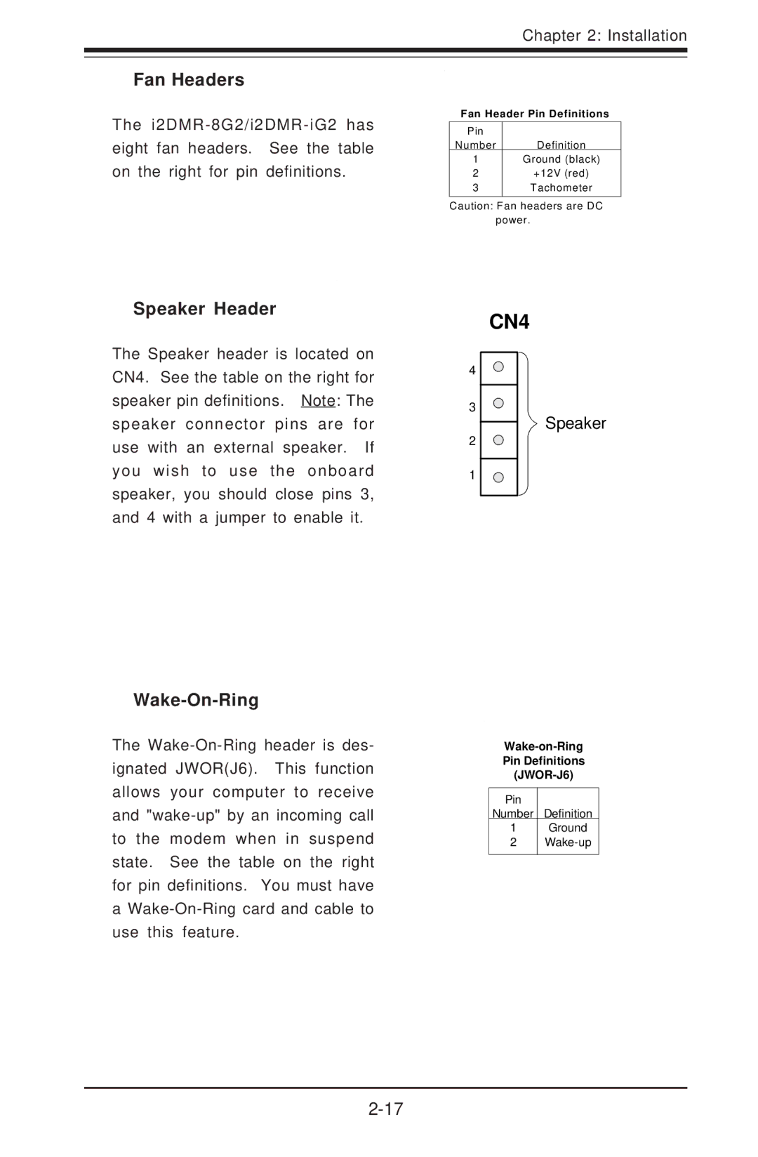
Speaker Header
The Speaker header is located on CN4. See the table on the right for speaker pin definitions. Note: The speaker connector pins are for use with an external speaker. If you wish to use the onboard speaker, you should close pins 3, and 4 with a jumper to enable it.
Fan Header Pin Definitions
Pin |
|
Number | Definition |
1Ground (black)
2+12V (red)
3Tachometer
Caution: Fan headers are DC power.
CN4
4
3
Speaker
2
1
Wake-On-Ring
The
a
Pin Definitions
Pin
Number Definition
1Ground
2