SCF418 Chassis Manual
B-6 Front Connector and Pin Definitions
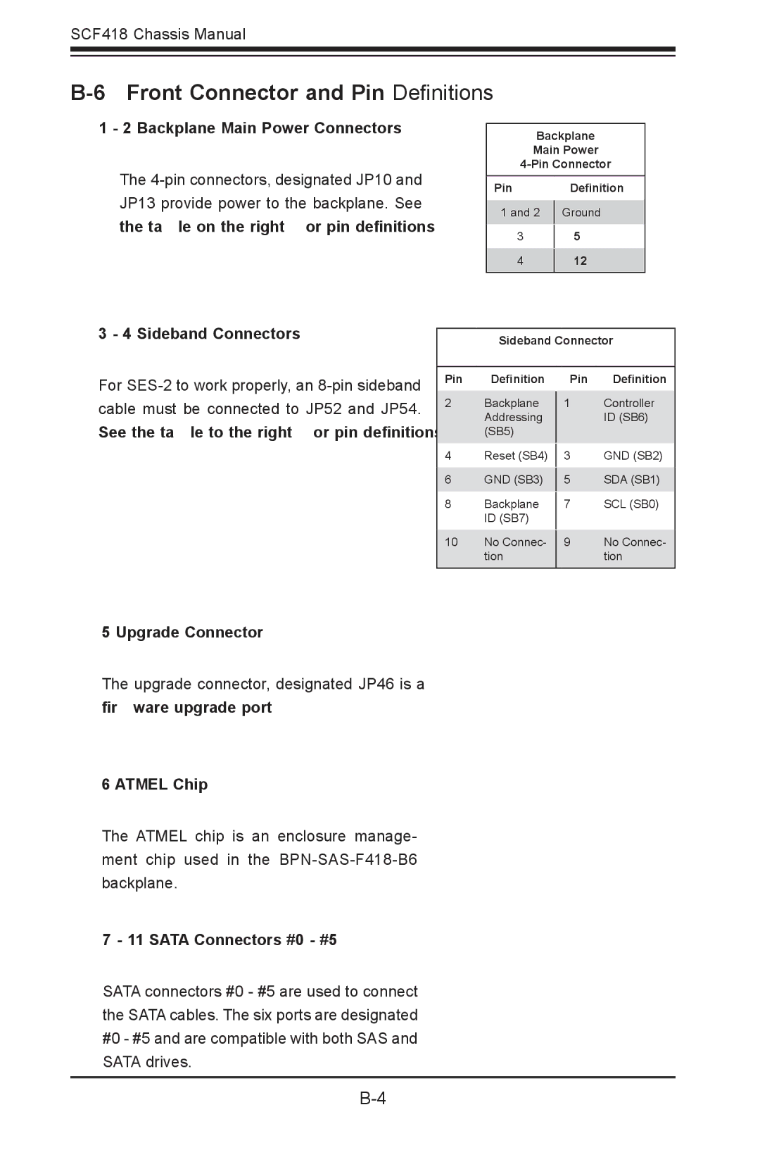
1 - 2 Backplane Main Power Connectors
The
Backplane
Main Power
Pin# Definition
1 and 2 | Ground |
|
|
3+5V
4+12V
3 - 4 Sideband Connectors
For
Sideband Connector
Pin # | Definition | Pin # | Definition |
2 | Backplane |
| Controller |
1 | |||
| Addressing |
| ID (SB6) |
| (SB5) |
|
|
4 | Reset (SB4) |
| GND (SB2) |
3 | |||
6 | GND (SB3) |
| SDA (SB1) |
5 | |||
8 | Backplane |
| SCL (SB0) |
7 | |||
| ID (SB7) |
|
|
10 | No Connec- |
| No Connec- |
9 | |||
| tion |
| tion |
|
|
|
|
5 Upgrade Connector
The upgrade connector, designated JP46 is a firmware upgrade port.
6 ATMEL Chip
The ATMEL chip is an enclosure manage- ment chip used in the
7 - 11 SATA Connectors #0 - #5
SATA connectors #0 - #5 are used to connect the SATA cables. The six ports are designated #0 - #5 and are compatible with both SAS and SATA drives.