VERTICAL VENT FIGURES/TABLES
Note: Secure Vent (rigid vent pipe) is shown in the figures; Secure Flex (flexible vent pipe) may also be used.
WARNING: UNDER NO CIRCUMSTANCES MAY SEPARATE SECTIONS OF CONCEN- TRIC FLEXIBLE VENT PIPE BE JOINED TOGETHER.
Note: It is very important that the horizontal/ inclined run be maintained in a straight (no dips) and recommended to be in a slightly elevated plane, in a direction away from the fireplace of ¹⁄₄" rise per foot (20 mm per meter) which is ideal, though rise per foot run ratios that are smaller are acceptable all the way down to at or near level.
| TABLE A |
|
|
| ||
|
|
|
|
|
| |
V MINIMUM | H Maximum |
|
| |||
|
|
|
|
|
| |
feet | (m) | feet | (m) |
|
| |
|
| |||||
|
|
|
|
|
| |
1 | (0.305) | 2 | (0.61) |
|
| |
|
|
|
|
|
| |
2 | (0.61) | 4 | (1.222) |
|
| |
|
|
|
|
|
| |
3 | (0.914) | 6 | (1.86) |
|
| |
V | ||||||
|
|
|
| |||
4 | (1.22) | 8 | (2.4) | |||
|
| |||||
|
| |||||
|
|
|
|
|
| |
V + H = 40 feet (12.4 m) Max. |
|
| ||||
H = 8 feet (2.4 m) Max. |
|
| ||||
|
|
|
|
|
| |
|
|
|
|
|
| |
| *When using Secure Flex, |
| use Firestop/Spacer |
*Ceiling | SF4.5BF |
**When using Secure | |
Firestop/Spacer | Flex, use Firestop/Spacer |
(SV4.5BF) | SF4.5HF |
**Wall
Firestop/Spacer
(SV4.5HF)
H
Note: SV4.5BF (Secure Vent), SF4.5BF (Secure Flex) firestop/spacer must be used anytime vent pipe passes through a combustible floor or ceil- ing. SV4.5HF (Secure Vent), SF4.5HF (Secure Flex)firestop/spacer must be used anytime vent pipe passes through a combustible wall.
Note: Two 45 degree elbows may be used in place of one 90 degree elbow. The same rise to run ratios, as shown in the venting figures for 90 elbows, must be followed if 45 degree elbows are used.
40 feet (12.2 meters)
*Ceiling ![]() Maximum Firestop/Spacer
Maximum Firestop/Spacer
(SV4.5BF)
*When using Secure Flex, use Firestop/Spacer SF4.5BF
Figure 23 - Top Vent - STRAIGHT
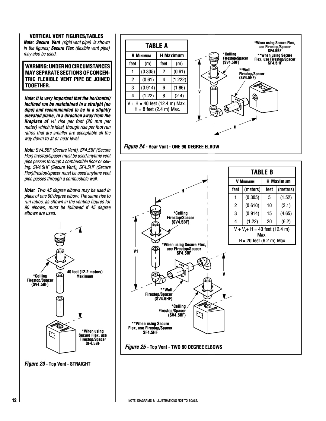
Figure 24 - Rear Vent - ONE 90 DEGREE ELBOW
|
|
| TABLE B |
| |
|
| V MINIMUM | H Maximum | ||
| H | feet | (meters) | feet | (meters) |
|
| 1 | (0.305) | 5 | (1.52) |
|
| 2 | (0.610) | 10 | (3.1) |
| *Ceiling | 3 | (0.914) | 15 | (4.65) |
| Firestop/Spacer | 4 | (1.22) | 20 | (6.2) |
| (SV4.5BF) | ||||
|
| V + V1+ H = 40 feet (12.4 m) | |||
|
|
| Max. |
| |
| *When using Secure Flex, | H = 20 feet (6.2 m) Max. | |||
|
|
|
|
| |
V1 | use Firestop/Spacer |
|
|
|
|
SF4.5BF |
|
|
|
| |
|
|
|
|
| |
|
| V |
|
|
|
| **Wall |
|
|
|
|
| Firestop/Spacer |
|
|
|
|
| (SV4.5HF) |
|
|
|
|
| *Ceiling |
|
|
|
|
| Firestop/Spacer |
|
|
|
|
| (SV4.5BF) |
|
|
|
|
**When using Secure |
|
|
|
| |
Flex, use Firestop/Spacer |
|
|
|
| |
| SF4.5HF |
|
|
|
|
Figure 25 - Top Vent - TWO 90 DEGREE ELBOWS |
|
|
|
| |
12
NOTE: DIAGRAMS & ILLUSTRATIONS NOT TO SCALE.