8
FIREPLACE SPECIFICATIONS |
|
|
|
|
|
| |||
FRAMING |
| 21¹⁄₂ |
|
| (Louvered Front Model Shown) |
|
|
| |
SPACERS | 10³⁄₄ | (546) |
|
|
|
|
|
| |
(Top and Sides |
|
|
| *CONCENTRIC FLUE |
|
|
| ||
and Rear) | (273) |
|
| FLUE - 4¹⁄₂ (114) |
|
|
| ||
|
|
|
|
| COMBUSTION AIR - 7¹⁄₂ (190) |
|
|
| |
|
|
|
|
|
| Inches (millimeters) | |||
|
|
|
|
| *DR models have only a rear vent |
|
|
| |
|
|
|
| 6¹³⁄₁₆ | *DT models have only a top vent |
|
|
| |
|
|
|
|
|
|
|
| ||
|
|
|
| (173) |
|
|
|
| |
| Top View |
|
|
|
|
|
| ||
|
|
|
|
|
| 13 |
|
| |
|
| 33¹⁄₈ |
| 3 (76) | NOTE - Eyebrow | (330) |
|
| |
|
|
| hood shown as positioned |
| ¹⁄₂ (13) |
| |||
|
| (841) |
|
| in louvered front model. |
|
| ||
|
|
|
|
| ELECTRICAL INLET |
|
|
| |
1 |
|
|
|
| 2³⁄₄ x 2 (70 x 51) |
|
|
| |
|
|
|
| COVER PLATE with |
|
|
| ||
(25) |
|
|
|
|
|
|
| ||
|
|
|
| KNOCKOUT) |
|
|
| ||
|
|
|
|
|
|
|
| ||
33¹⁄₈ |
|
| 17 | 30¹⁄₈ | GAS INLET |
| 1 (25) |
| |
| 27¹⁄₂ | (432) | (765) | 8¹¹⁄₃₂ |
| **19⁵⁄₈ | |||
(841) |
| (Either Side |
| ||||||
|
|
| (212) |
| |||||
| (699) |
|
| 1⁵⁄₈ | |||||
|
|
|
| and bottom) |
| (498) | |||
|
|
|
|
| 3 (76) |
| (42) |
| |
|
|
|
|
|
|
|
| ||
| Front View |
|
|
| 2³⁄₄ **Rear vent models only | ||||
|
| Right Side View | (70) |
| |||||
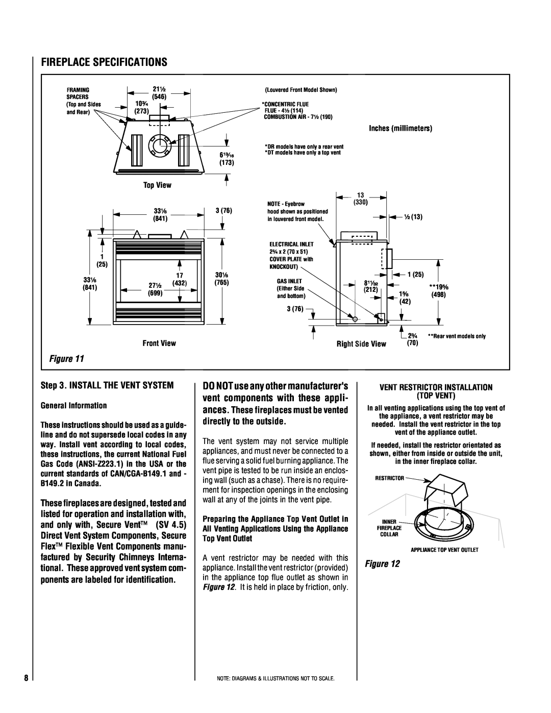
Figure 11 |
|
|
|
|
|
|
|
| |
Step 3. INSTALL THE VENT SYSTEM | DO NOT use any other manufacturer's | VENT RESTRICTOR INSTALLATION | |||||||
General Information |
|
|
| vent components with these appli- |
| (TOP VENT) | |||
|
|
| ances. These fireplaces must be vented | In all venting applications using the top vent of | |||||
|
|
|
| ||||||
|
|
|
| directly to the outside. | the appliance, a vent restrictor may be | ||||
These instructions should be used as a guide- | needed. Install the vent restrictor in the top | ||||||||
|
| ||||||||
line and do not supersede local codes in any | The vent system | may not service multiple |
| vent of the appliance outlet. | |||||
way. Install vent according to local codes, | If needed, install the restrictor orientated as | ||||||||
appliances, and must never be connected to a | |||||||||
these instructions, the current National Fuel | shown, either from inside or outside the unit, | ||||||||
flue serving a solid fuel burning appliance. The | |||||||||
Gas Code |
| in the inner fireplace collar. | |||||||
vent pipe is tested to be run inside an enclos- |
|
|
| ||||||
current standards of | RESTRICTOR |
| |||||||
ing wall (such as a chase). There is no require- |
| ||||||||
B149.2 in Canada. |
|
|
|
| |||||
|
|
|
|
|
| ||||
|
|
| ment for inspection openings in the enclosing |
|
|
| |||
|
|
|
|
|
|
| |||
These fireplaces are designed, tested and | wall at any of the joints in the vent pipe. |
|
|
| |||||
|
|
|
|
| |||||
listed for operation and installation with, | Preparing the Appliance Top Vent Outlet in | INNER |
| ||||||
and only with, Secure Vent™ | (SV 4.5) |
| |||||||
All Venting Applications Using the Appliance | FIREPLACE |
| |||||||
Direct Vent System Components, Secure |
| ||||||||
Top Vent Outlet |
| COLLAR |
| ||||||
|
|
|
|
|
|
| |||
Flex™ Flexible Vent Components manu- |
|
|
| APPLIANCE TOP VENT OUTLET | |||||
factured by Security Chimneys Interna- | A vent restrictor | may be needed with this | Figure 12 |
| |||||
tional. These approved vent system com- | appliance. Install the vent restrictor (provided) |
| |||||||
|
|
| |||||||
ponents are labeled for identification. | in the appliance top flue outlet as shown in |
|
|
| |||||
|
|
|
| Figure 12. It is held in place by friction, only. |
|
|
| ||
NOTE: DIAGRAMS & ILLUSTRATIONS NOT TO SCALE.