| VENT | REARVENT | APPLICATION | REAR | |
TOP |
| VENT | |||
|
| ||||
| APPLICATION | ||||
APPLICATION |
|
| |||
|
|
| APPLICATION | ||
APPLICATION |
| TOP VENT | TOP VENT TOP VENT | ||
TOP VENT |
|
| APPLICATION | ||
| RECESSED | ||||
| INSTALLATIONAPPLICATION | ||||
|
|
| TOP VENT |
|
|
|
|
| APPLICATION |
| |
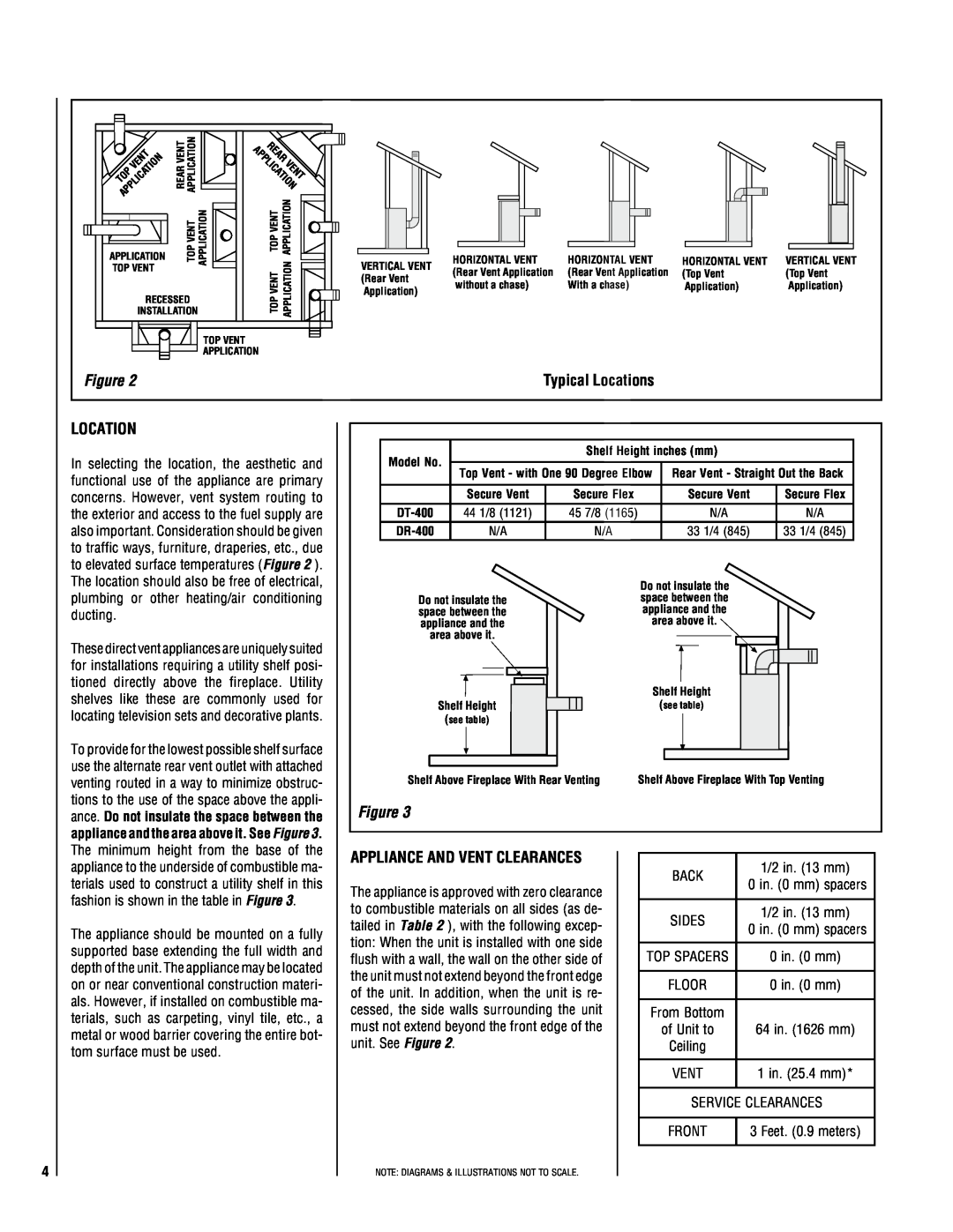
Figure 2
VERTICAL VENT
(Rear Vent
Application)
HORIZONTAL VENT | HORIZONTAL VENT | HORIZONTAL VENT | VERTICAL VENT |
(Rear Vent Application | (Rear Vent Application | (Top Vent | (Top Vent |
without a chase) | With a chase) | Application) | Application) |
Typical Locations
LOCATION
In selecting the location, the aesthetic and functional use of the appliance are primary concerns. However, vent system routing to the exterior and access to the fuel supply are also important. Consideration should be given to traffic ways, furniture, draperies, etc., due to elevated surface temperatures (Figure 2 ). The location should also be free of electrical,
Model No. |
| Shelf Height inches (mm) |
| ||
|
|
|
| ||
Top Vent - with One 90 Degree Elbow | Rear Vent - Straight Out the Back | ||||
| |||||
|
|
|
|
| |
| Secure Vent | Secure Flex | Secure Vent | Secure Flex | |
44 1/8 (1121) | 45 7/8 (1165) | N/A | N/A | ||
N/A | N/A | 33 1/4 (845) | 33 1/4 (845) | ||
plumbing or other heating/air conditioning ducting.
These direct vent appliances are uniquely suited for installations requiring a utility shelf posi- tioned directly above the fireplace. Utility shelves like these are commonly used for locating television sets and decorative plants.
Do not insulate the space between the appliance and the area above it.
Shelf Height
(see table)
Do not insulate the space between the appliance and the area above it.
Shelf Height
(see table)
To provide for the lowest possible shelf surface use the alternate rear vent outlet with attached venting routed in a way to minimize obstruc- tions to the use of the space above the appli- ance. Do not insulate the space between the appliance and the area above it. See Figure 3. The minimum height from the base of the
Shelf Above Fireplace With Rear Venting | Shelf Above Fireplace With Top Venting |
Figure 3
appliance to the underside of combustible ma- terials used to construct a utility shelf in this fashion is shown in the table in Figure 3.
The appliance should be mounted on a fully supported base extending the full width and depth of the unit. The appliance may be located on or near conventional construction materi- als. However, if installed on combustible ma- terials, such as carpeting, vinyl tile, etc., a metal or wood barrier covering the entire bot- tom surface must be used.
APPLIANCE AND VENT CLEARANCES
The appliance is approved with zero clearance to combustible materials on all sides (as de- tailed in Table 2 ), with the following excep- tion: When the unit is installed with one side flush with a wall, the wall on the other side of the unit must not extend beyond the front edge of the unit. In addition, when the unit is re- cessed, the side walls surrounding the unit must not extend beyond the front edge of the unit. See Figure 2.
BACK | 1/2 in. (13 mm) | |
0 in. (0 mm) spacers | ||
| ||
|
| |
SIDES | 1/2 in. (13 mm) | |
0 in. (0 mm) spacers | ||
| ||
|
| |
TOP SPACERS | 0 in. (0 mm) | |
|
| |
FLOOR | 0 in. (0 mm) | |
|
| |
From Bottom |
| |
of Unit to | 64 in. (1626 mm) | |
Ceiling |
| |
|
| |
VENT | 1 in. (25.4 mm)* | |
|
| |
SERVICE CLEARANCES | ||
|
| |
FRONT | 3 Feet. (0.9 meters) | |
|
| |
4
NOTE: DIAGRAMS & ILLUSTRATIONS NOT TO SCALE.