VERTICAL VENT FIGURES/TABLES
(continued)
|
| TABLE D |
|
|
|
|
| |
|
|
|
|
|
|
|
| |
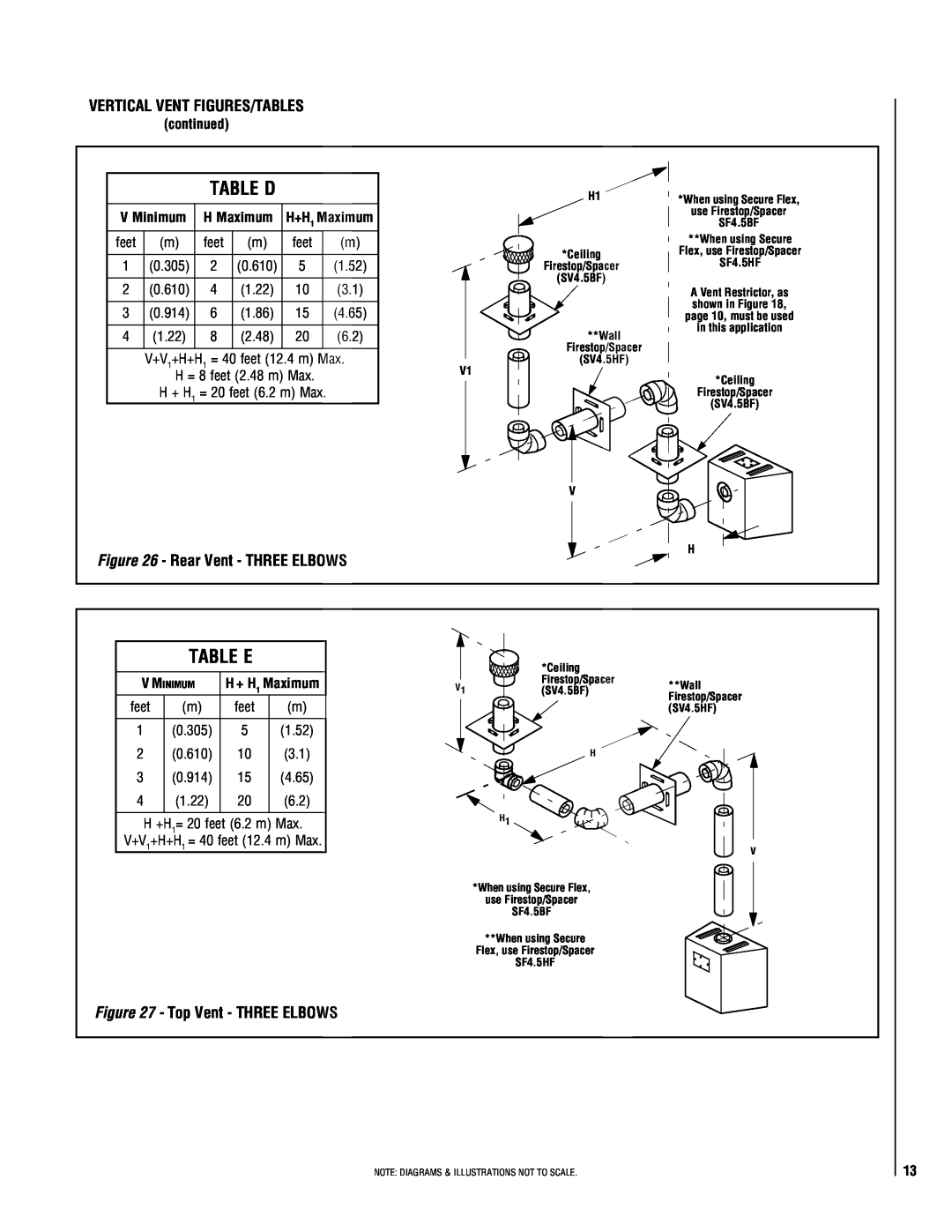
V Minimum | H Maximum | H+H1 Maximum |
|
| ||||
feet | (m) | feet | (m) | feet |
| (m) |
|
|
|
|
|
|
|
|
|
|
|
1 | (0.305) | 2 | (0.610) | 5 |
| (1.52) |
|
|
|
|
|
|
|
|
|
|
|
2 | (0.610) | 4 | (1.22) | 10 |
| (3.1) |
|
|
|
|
|
|
|
|
|
|
|
3 | (0.914) | 6 | (1.86) | 15 |
| (4.65) |
|
|
|
|
|
|
|
|
|
|
|
4 | (1.22) | 8 | (2.48) | 20 |
| (6.2) |
|
|
|
|
|
|
|
|
|
| |
| V+V1+H+H1 = 40 feet (12.4 m) Max. |
|
| |||||
| V1 | |||||||
| H = 8 feet (2.48 m) Max. |
| ||||||
| H + H1 = 20 feet (6.2 m) Max. |
|
|
| ||||
|
|
|
|
|
|
|
|
|
H1
*Ceiling
Firestop/Spacer
(SV4.5BF)
**Wall
Firestop/Spacer
(SV4.5HF)
*When using Secure Flex, use Firestop/Spacer SF4.5BF
**When using Secure Flex, use Firestop/Spacer SF4.5HF
A Vent Restrictor, as shown in Figure 18, page 10, must be used in this application
*Ceiling
Firestop/Spacer
(SV4.5BF)
V
Figure 26 - Rear Vent - THREE ELBOWS
H
TABLE E
V MINIMUM | H + H1 Maximum | ||
feet | (m) | feet | (m) |
1 | (0.305) | 5 | (1.52) |
2 | (0.610) | 10 | (3.1) |
3 | (0.914) | 15 | (4.65) |
4 | (1.22) | 20 | (6.2) |
H +H1= 20 feet (6.2 m) Max.
V+V1+H+H1 = 40 feet (12.4 m) Max.
Figure 27 - Top Vent - THREE ELBOWS
| *Ceiling |
|
V1 | Firestop/Spacer | **Wall |
(SV4.5BF) | ||
|
| Firestop/Spacer |
|
| (SV4.5HF) |
| H |
|
H1
V
*When using Secure Flex, use Firestop/Spacer SF4.5BF
**When using Secure Flex, use Firestop/Spacer SF4.5HF
NOTE: DIAGRAMS & ILLUSTRATIONS NOT TO SCALE.
13