Select Venting System - Horizontal or Vertical
With the appliance secured in framing, deter- mine vent routing and identify the exterior termination location. The following sections describe vertical (roof) and horizontal (exterior wall) vent applications. Refer to the section relating to your installation. A list of approved venting components is shown in the tables on pages 24 and 25.
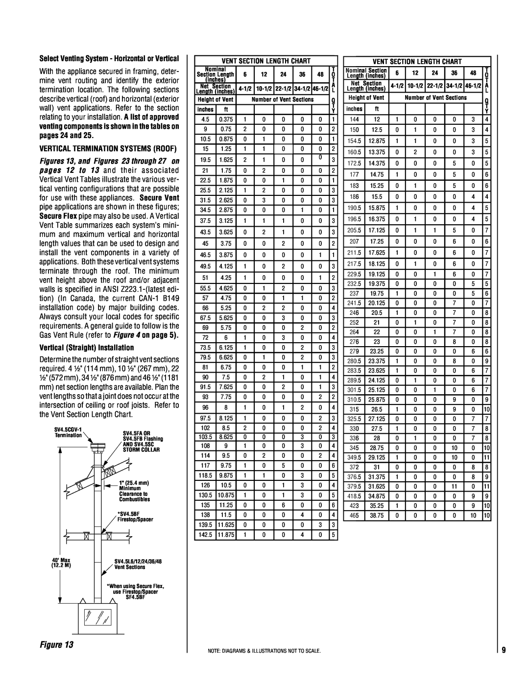
VERTICAL TERMINATION SYSTEMS (ROOF)
Figures 13, and Figures 23 through 27 on pages 12 to 13 and their associated Vertical Vent Tables illustrate the various ver- tical venting configurations that are possible for use with these appliances. Secure Vent pipe applications are shown in these figures; Secure Flex pipe may also be used. A Vertical Vent Table summarizes each system’s mini- mum and maximum vertical and horizontal length values that can be used to design and install the vent components in a variety of applications. Both these vertical vent systems terminate through the roof. The minimum vent height above the roof and/or adjacent walls is specified in ANSI
Vertical (Straight) Installation
Determine the number of straight vent sections required. 4 ¹⁄₂" (114 mm), 10 ¹⁄₂" (267 mm), 22 ¹⁄₂" (572 mm), 34 ¹⁄₂" (876 mm) and 46 ¹⁄₂" (1181
mm)net section lengths are available. Plan the vent lengths so that a joint does not occur at the intersection of ceiling or roof joists. Refer to the Vent Section Length Chart.
SV4.5FA OR | ||
Termination | ||
SV4.5FB Flashing | ||
| ||
| AND SV4.5SC | |
| STORM COLLAR |
|
|
| 1" (25.4 mm) | |
|
|
| Minimum | |
|
|
| Clearance to | |
|
|
| Combustibles | |
|
|
| *SV4.5BF | |
|
|
| Firestop/Spacer | |
40' | Max | SV4.5L6/12/24/36/48 | ||
(12.2 | M) | |||
Vent Sections | ||||
|
|
| ||
|
|
| *When using Secure Flex, | |
|
|
| use Firestop/Spacer | |
|
|
| SF4.5BF | |
| VENT SECTION LENGTH CHART |
|
| ||||||
Nominal | 6 |
| 12 | 24 | 36 |
| 48 | T | |
Section Length |
|
| O | ||||||
(inches) |
|
|
|
|
|
|
| T | |
Net Section |
| A | |||||||
Length (inches) |
| L | |||||||
Height of Vent |
| Number of Vent Sections |
| Q | |||||
|
|
|
|
|
|
|
|
| T |
inches | ft |
|
|
|
|
|
|
| |
|
|
|
|
|
|
| Y | ||
4.5 | 0.375 | 1 |
| 0 | 0 | 0 |
| 0 | 1 |
9 | 0.75 | 2 |
| 0 | 0 | 0 |
| 0 | 2 |
10.5 | 0.875 | 0 |
| 1 | 0 | 0 |
| 0 | 1 |
|
|
|
|
|
|
|
|
|
|
15 | 1.25 | 1 |
| 1 | 0 | 0 |
| 0 | 2 |
|
|
|
|
|
|
|
|
|
|
19.5 | 1.625 | 2 |
| 1 | 0 | 0 |
| 0 | 3 |
|
|
| |||||||
|
|
|
|
|
|
|
|
|
|
21 | 1.75 | 0 |
| 2 | 0 | 0 |
| 0 | 2 |
22.5 | 1.875 | 0 |
| 0 | 1 | 0 |
| 0 | 1 |
|
|
|
|
|
|
|
|
|
|
25.5 | 2.125 | 1 |
| 2 | 0 | 0 |
| 0 | 3 |
|
|
|
|
|
|
|
|
|
|
31.5 | 2.625 | 0 |
| 3 | 0 | 0 |
| 0 | 3 |
|
|
|
|
|
|
|
|
|
|
34.5 | 2.875 | 0 |
| 0 | 0 | 1 |
| 0 | 1 |
37.5 | 3.125 | 1 |
| 1 | 1 | 0 |
| 0 | 3 |
|
|
|
|
|
|
|
|
|
|
43.5 | 3.625 | 0 |
| 2 | 1 | 0 |
| 0 | 3 |
|
|
|
|
|
|
|
|
|
|
45 | 3.75 | 0 |
| 0 | 2 | 0 |
| 0 | 2 |
|
|
|
|
|
|
|
|
|
|
46.5 | 3.875 | 0 |
| 0 | 0 | 0 |
| 1 | 1 |
|
|
|
|
|
|
|
|
|
|
49.5 | 4.125 | 1 |
| 0 | 2 | 0 |
| 0 | 3 |
|
|
|
|
|
|
|
|
|
|
51 | 4.25 | 1 |
| 0 | 0 | 0 |
| 1 | 2 |
|
|
|
|
|
|
|
|
|
|
55.5 | 4.625 | 0 |
| 1 | 2 | 0 |
| 0 | 3 |
57 | 4.75 | 0 |
| 0 | 1 | 1 |
| 0 | 2 |
66 | 5.25 | 0 |
| 2 | 2 | 0 |
| 0 | 4 |
|
|
|
|
|
|
|
|
|
|
67.5 | 5.625 | 0 |
| 0 | 3 | 0 |
| 0 | 3 |
|
|
|
|
|
|
|
|
|
|
69 | 5.75 | 0 |
| 0 | 0 | 2 |
| 0 | 2 |
72 | 6 | 1 |
| 0 | 3 | 0 |
| 0 | 4 |
73.5 | 6.125 | 1 |
| 0 | 0 | 2 |
| 0 | 3 |
|
|
|
|
|
|
|
|
|
|
79.5 | 6.625 | 0 |
| 1 | 0 | 2 |
| 0 | 3 |
|
|
|
|
|
|
|
|
|
|
81 | 6.75 | 0 |
| 0 | 0 | 1 |
| 1 | 2 |
90 | 7.5 | 0 |
| 2 | 1 | 0 |
| 1 | 4 |
91.5 | 7.625 | 0 |
| 0 | 2 | 0 |
| 1 | 3 |
|
|
|
|
|
|
|
|
|
|
93 | 7.75 | 0 |
| 0 | 0 | 0 |
| 2 | 2 |
|
|
|
|
|
|
|
|
|
|
96 | 8 | 1 |
| 0 | 1 | 2 |
| 0 | 4 |
|
|
|
|
|
|
|
|
|
|
97.5 | 8.125 | 1 |
| 0 | 0 | 0 |
| 2 | 3 |
|
|
|
|
|
|
|
|
|
|
102 | 8.5 | 2 |
| 0 | 0 | 0 |
| 2 | 4 |
|
|
|
|
|
|
|
|
|
|
103.5 | 8.625 | 0 |
| 0 | 0 | 3 |
| 0 | 3 |
108 | 9 | 1 |
| 0 | 0 | 3 |
| 0 | 4 |
114 | 9.5 | 0 |
| 2 | 0 | 0 |
| 2 | 4 |
|
|
|
|
|
|
|
|
|
|
117 | 9.75 | 1 |
| 0 | 5 | 0 |
| 0 | 6 |
|
|
|
|
|
|
|
|
|
|
118.5 | 9.875 | 1 |
| 1 | 0 | 3 |
| 0 | 5 |
|
|
|
|
|
|
|
|
|
|
126 | 10.5 | 0 |
| 0 | 1 | 3 |
| 0 | 4 |
130.5 | 10.875 | 1 |
| 0 | 1 | 3 |
| 0 | 5 |
|
|
|
|
|
|
|
|
|
|
135 | 11.25 | 0 |
| 0 | 6 | 0 |
| 0 | 6 |
|
|
|
|
|
|
|
|
|
|
138 | 11.5 | 0 |
| 0 | 0 | 4 |
| 0 | 4 |
|
|
|
|
|
|
|
|
|
|
139.5 | 11.625 | 0 |
| 0 | 0 | 0 |
| 3 | 3 |
142.5 | 11.875 | 1 |
| 0 | 0 | 4 |
| 0 | 5 |
|
|
|
|
|
|
|
|
|
|
|
| VENT SECTION LENGTH CHART |
|
| |||||
Nominal Section | 6 |
| 12 | 24 | 36 | 48 | T | ||
Length (inches) |
| O | |||||||
|
|
|
|
|
|
|
|
| T |
Net | Section |
|
|
|
|
|
| ||
| A | ||||||||
Length (inches) |
| ||||||||
|
|
|
|
|
| L | |||
Height of Vent |
| Number of Vent Sections | Q | ||||||
|
|
|
|
|
|
|
|
| |
inches |
| ft |
|
|
|
|
|
| T |
|
|
|
|
|
|
| Y | ||
|
|
|
|
|
|
|
|
| |
144 |
| 12 | 1 |
| 0 | 0 | 0 | 3 | 4 |
150 |
| 12.5 | 0 |
| 1 | 0 | 0 | 3 | 4 |
|
|
|
|
|
|
|
|
|
|
154.5 |
| 12.875 | 1 |
| 1 | 0 | 0 | 3 | 5 |
|
|
|
|
|
|
|
|
|
|
160.5 |
| 13.375 | 0 |
| 2 | 0 | 0 | 3 | 5 |
|
|
|
|
|
|
|
|
|
|
172.5 |
| 14.375 | 0 |
| 0 | 0 | 5 | 0 | 5 |
|
|
|
|
|
|
|
|
|
|
177 |
| 14.75 | 1 |
| 0 | 0 | 5 | 0 | 6 |
|
|
|
|
|
|
|
|
|
|
183 |
| 15.25 | 0 |
| 1 | 0 | 5 | 0 | 6 |
|
|
|
|
|
|
|
|
|
|
186 |
| 15.5 | 0 |
| 0 | 0 | 0 | 4 | 4 |
|
|
|
|
|
|
|
|
|
|
190.5 |
| 15.875 | 1 |
| 0 | 0 | 0 | 4 | 5 |
|
|
|
|
|
|
|
|
|
|
196.5 |
| 16.375 | 0 |
| 1 | 0 | 0 | 4 | 5 |
|
|
|
|
|
|
|
|
|
|
205.5 |
| 17.125 | 0 |
| 1 | 1 | 5 | 0 | 7 |
|
|
|
|
|
|
|
|
|
|
207 |
| 17.25 | 0 |
| 0 | 0 | 6 | 0 | 6 |
|
|
|
|
|
|
|
|
|
|
211.5 |
| 17.625 | 1 |
| 0 | 0 | 6 | 0 | 7 |
|
|
|
|
|
|
|
|
|
|
217.5 |
| 18.125 | 0 |
| 1 | 0 | 6 | 0 | 7 |
|
|
|
|
|
|
|
|
|
|
229.5 |
| 19.125 | 0 |
| 0 | 1 | 6 | 0 | 7 |
232.5 |
| 19.375 | 0 |
| 0 | 0 | 0 | 5 | 5 |
237 |
| 19.75 | 1 |
| 0 | 0 | 0 | 5 | 6 |
241.5 |
| 20.125 | 0 |
| 0 | 0 | 7 | 0 | 7 |
|
|
|
|
|
|
|
|
|
|
246 |
| 20.5 | 1 |
| 0 | 0 | 7 | 0 | 8 |
|
|
|
|
|
|
|
|
|
|
252 |
| 21 | 0 |
| 1 | 0 | 7 | 0 | 8 |
|
|
|
|
|
|
|
|
|
|
264 |
| 22 | 0 |
| 0 | 1 | 7 | 0 | 8 |
|
|
|
|
|
|
|
|
|
|
276 |
| 23 | 0 |
| 0 | 0 | 8 | 0 | 8 |
279 |
| 23.25 | 0 |
| 0 | 0 | 0 | 6 | 6 |
280.5 |
| 23.375 | 1 |
| 0 | 0 | 8 | 0 | 9 |
283.5 |
| 23.625 | 1 |
| 0 | 0 | 0 | 6 | 7 |
289.5 |
| 24.125 | 0 |
| 1 | 0 | 0 | 6 | 7 |
301.5 |
| 25.125 | 0 |
| 0 | 1 | 0 | 6 | 7 |
310.5 |
| 25.875 | 0 |
| 0 | 0 | 9 | 0 | 9 |
|
|
|
|
|
|
|
|
|
|
315 |
| 26.5 | 1 |
| 0 | 0 | 9 | 0 | 10 |
|
|
|
|
|
|
|
|
|
|
325.5 |
| 27.125 | 0 |
| 0 | 0 | 0 | 7 | 7 |
|
|
|
|
|
|
|
|
|
|
330 |
| 27.5 | 1 |
| 0 | 0 | 0 | 7 | 8 |
|
|
|
|
|
|
|
|
|
|
336 |
| 28 | 0 |
| 1 | 0 | 0 | 7 | 8 |
345 |
| 28.75 | 0 |
| 0 | 0 | 10 | 0 | 10 |
349.5 |
| 29.125 | 1 |
| 0 | 0 | 10 | 0 | 11 |
372 |
| 31 | 0 |
| 0 | 0 | 0 | 8 | 8 |
376.5 |
| 31.375 | 1 |
| 0 | 0 | 0 | 8 | 9 |
379.5 |
| 31.625 | 0 |
| 0 | 0 | 11 | 0 | 11 |
418.5 |
| 34.875 | 0 |
| 0 | 0 | 0 | 9 | 9 |
|
|
|
|
|
|
|
|
|
|
423 |
| 35.25 | 1 |
| 0 | 0 | 0 | 9 | 10 |
|
|
|
|
|
|
|
|
|
|
465 |
| 38.75 | 0 |
| 0 | 0 | 0 | 10 | 10 |
|
|
|
|
|
|
|
|
|
|
Figure 13
NOTE: DIAGRAMS & ILLUSTRATIONS NOT TO SCALE.
9