worktop because if it becomes neces- sary to remove the hob from its position, the glass could break when trying to detach it.
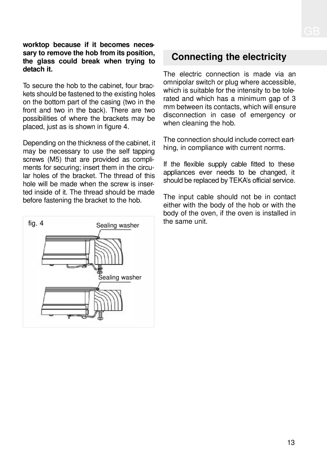
To secure the hob to the cabinet, four brac- kets should be fastened to the existing holes on the bottom part of the casing (two in the front and two in the back). There are two possibilities of where the brackets may be placed, just as is shown in figure 4.
Depending on the thickness of the cabinet, it may be necessary to use the self tapping screws (M5) that are provided as compli- ments for securing; insert them in the circu- lar holes of the bracket. The thread of this hole will be made when the screw is inser- ted inside of it. The thread should be made before fastening the bracket to the hob.
fig. 4 | Sealing washer |
Sealing washer
GB
Connecting the electricity
The electric connection is made via an omnipolar switch or plug where accessible, which is suitable for the intensity to be tole- rated and which has a minimum gap of 3
mmbetween its contacts, which will ensure disconnection in case of emergency or when cleaning the hob.
The connection should include correct eart- hing, in compliance with current norms.
If the flexible supply cable fitted to these appliances ever needs to be changed, it should be replaced by TEKA’s official service.
The input cable should not be in contact either with the body of the hob or with the body of the oven, if the oven is installed in the same unit.
13