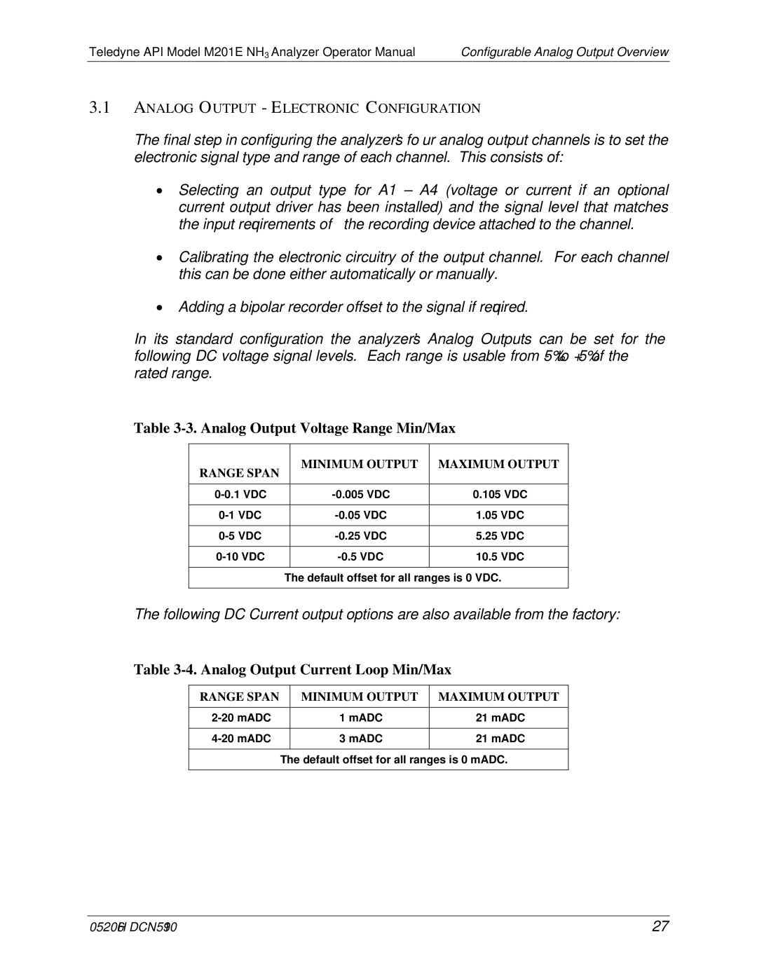
M201E specifications
The Teledyne M201E is a high-performance, compact oceanographic and environmental monitoring device designed for versatile underwater applications. Leveraging advanced technologies, the M201E presents a plethora of features appealing to researchers, engineers, and environmentalists seeking reliable data collection in challenging aquatic environments.One of the standout characteristics of the M201E is its robust design, which allows it to operate in various underwater conditions, from shallow coastal regions to deep-sea environments. Built with durable materials, the device ensures long-term performance and resilience against corrosion, making it an ideal choice for long-term deployments.
The M201E is equipped with a range of sophisticated sensors, enabling it to collect comprehensive data on several environmental parameters. Key features include the ability to measure temperature, salinity, depth, and turbidity, among others. This multi-parameter capability allows for detailed assessments of underwater ecosystems and provides essential insights into vital oceanographic processes.
Another remarkable aspect of the M201E is its connectivity and data transmission technologies. It supports various communication protocols, enabling real-time data streaming to research teams, enhancing their ability to respond to changing conditions swiftly. The device can be integrated into larger networks of sensors, facilitating a more extensive monitoring system that collaborates and shares valuable data.
Moreover, the M201E is powered by advanced battery technologies that maximize operational longevity, allowing for extended missions without the need for frequent maintenance. Users can also benefit from intuitive user interfaces and software, streamlining the process of configuring the device, managing data, and analyzing results.
The M201E’s versatility is further demonstrated by its compatibility with various mounting options and its adaptability to different research or monitoring projects. Whether deployed by autonomous underwater vehicles (AUVs), buoys, or fixed platforms, the M201E meets diverse field requirements.
In conclusion, the Teledyne M201E stands out as a highly functional and reliable tool for underwater research. With its robust design, comprehensive sensing capabilities, advanced communications technologies, and ease of integration, it significantly contributes to our understanding of marine and freshwater environments. As the demand for precise and reliable environmental monitoring continues to grow, the M201E is poised to play a crucial role in the future of oceanographic research and environmental management.

