Installing the Hardware
1.2 Installing the Hardware
To install the programming adapter hardware, perform the following steps:
1)Using the
2)Connect an external power supply to the programming adapter. The voltage of the power supply must be between 14 V and 20 V dc and must provide a minimum of 200 mA of power. The center terminal of the supply connector at the programming adapter is the plus pole.
3)The red LED on the programming adapter lights if the power supply is properly connected. If the LED does not light and the power supply is properly connected, check the F1 fuse on the programming adapter
4)The MSP430 devices, in a socket or on a PWB, should be connected to the programming adapter through the
The programming adapter provides the selected supply voltage VCC at pin 14 of the
supply the MSP430 device. The signal name is VCC_MSP.
If an external supply voltage VCC is used for the MSP430, the internal voltage VCC_MSP must be set to the same voltage level.
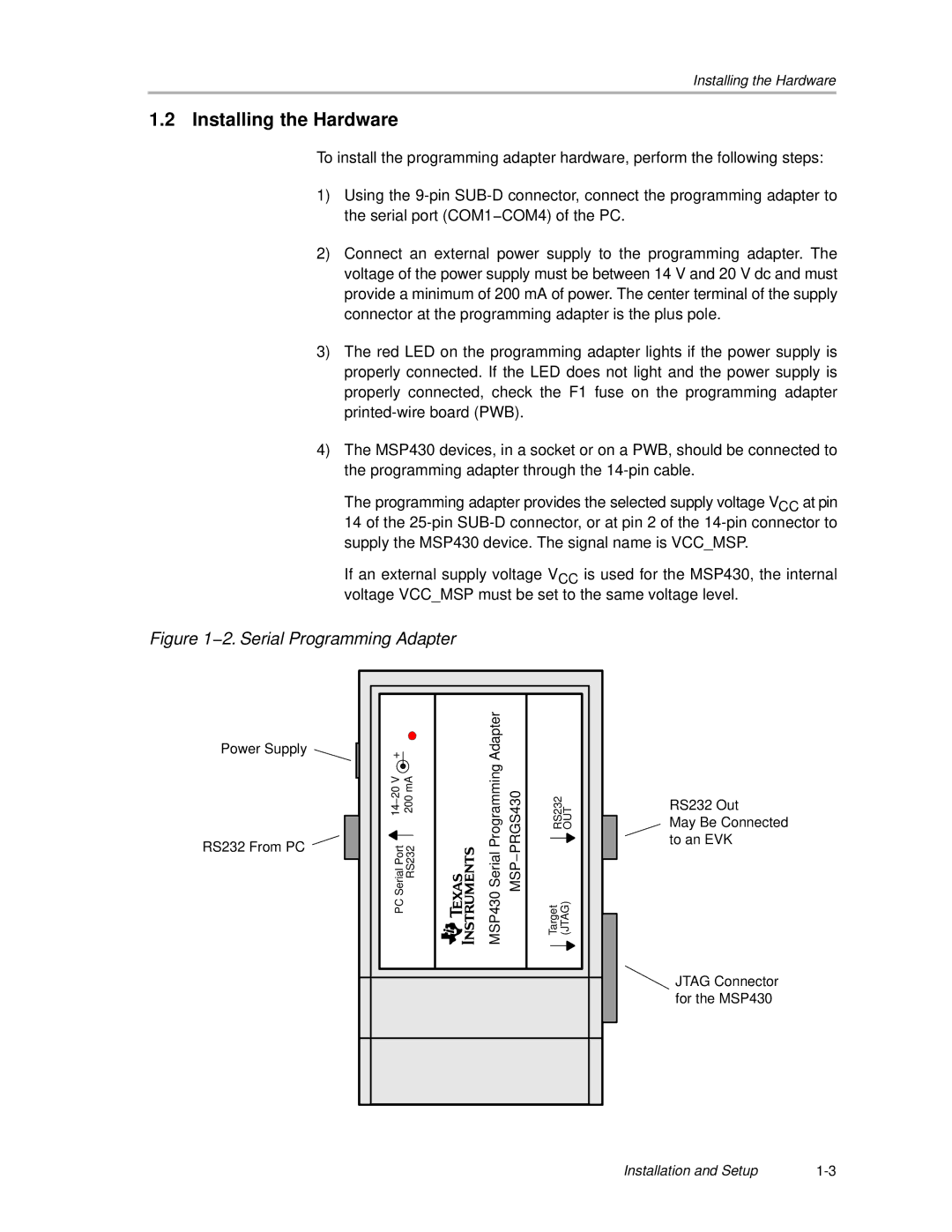
Figure 1−2. Serial Programming Adapter
Power Supply
RS232 From PC
|
| Adapter |
|
|
|
14−20 V | 200 mA | MSP430 Serial Programming | MSP−PRGS430 | RS232 OUT | |
PC Serial Port | RS232 | Target | (JTAG) | ||
RS232 Out
May Be Connected to an EVK
JTAG Connector for the MSP430
Installation and Setup |