Manuals
/
Texas Instruments
/
Home Audio
/
Speaker System
Texas Instruments
TAS3002
manual
… … … …, Digital Output Modes
Models:
TAS3002
1
10
54
54
Download
54 pages
10.85 Kb
7
8
9
10
11
12
13
14
Specs
1.3Functional Block Diagram
7.2.2Reset
Soft Volume Update
Power-DownMode
1.2Features
Switching Characteristics
Page 10
Image 10
Page 9
Page 11
Page 10
Image 10
Page 9
Page 11
Contents
Digital Audio Processor With Codec
Data Manual
TAS3002
2001
IMPORTANT NOTICE
1 Introduction
1.2Features
1.1 Description
1.3Functional Block Diagram
Figure 1−1. TAS3002 Block Diagram
Figure 1−2. TAS3002 Terminal Assignments
1.4 Terminal Assignments
1.5 Terminal Functions
Table 1−1. TAS3002 Terminal Functions
Table 1−1. TAS3002 Terminal Functions Continued
Page
2.1 Serial Interface Formats
2 Audio Data Formats
Table 2−1. Serial Interface Options
… … … …
… … … …
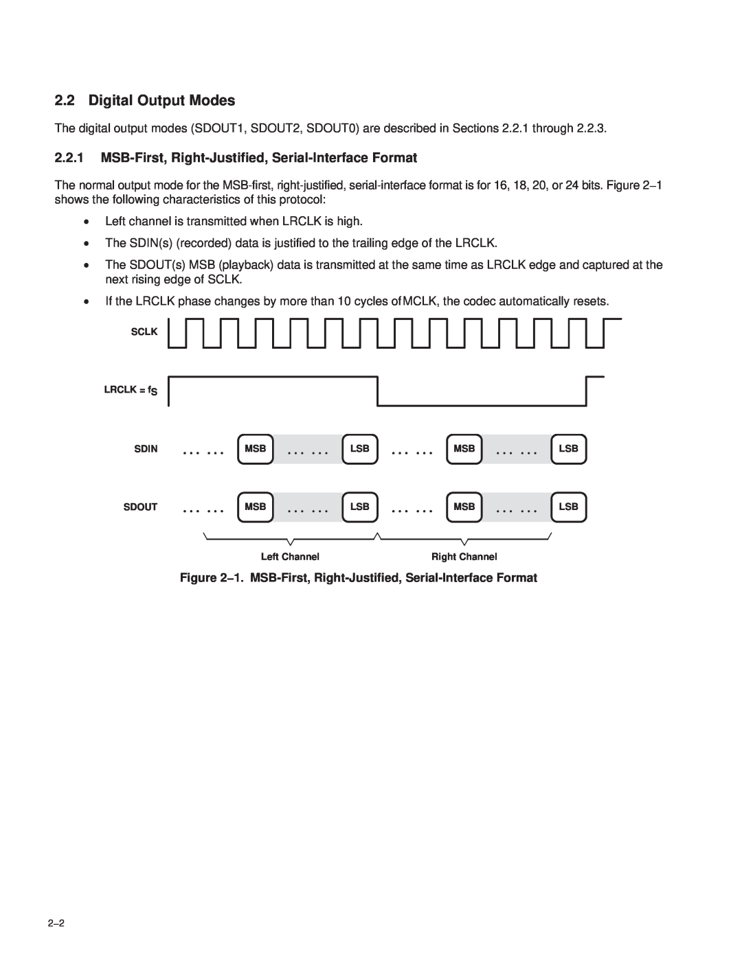
2.2 Digital Output Modes
… … … …
… … … …
2.2.2I2S Serial-InterfaceFormat
Figure 2−2. I 2S Serial-InterfaceFormat
… … … …
… … … …
2.2.3MSB-Left-Justified, Serial-InterfaceFormat
… … … …
… … … …
UNIT
2.3 Switching Characteristics
PARAMETER
tcSCLK SCLK LRCLK tdSDOUT SDOUT1 SDOUT2 SDOUT0
Page
3.2 Analog Output
3 Analog Input/Output
3.1 Analog Input
3.2.1Direct Analog Output
Figure 3−2. VCOM Decoupling Network
3.2.2Analog Output With Gain
Figure 3−3. Analog Output With External Amplifier
TAS3002
3.2.3Reference Voltage Filter
Figure 3−4. TAS3002 Reference Voltage Filter
Page
4.2 Software Soft Mute
4.1 Soft Volume Update
4 Audio Control/Enhancement Functions
4.3 Input Mixer Control
4.5 Treble Control
4.4 Mono Mixer Control
Figure 4−1. TAS3002 Mixer Function
4.7 De-EmphasisMode DM
4.6 Bass Control
Figure 4−2. De-EmphasisMode Frequency Response
4.8 Analog Control Register 40h
Table 4−1. Analog Control Register Description
4.9.2Loudness Gain
4.9 Dynamic Loudness Contour
4.9.1Loudness Biquads
4.9.3Loudness Contour Operation
4.10 Dynamic Range Compression/Expansion DRCE
4.11 AllPass Function
Table 4−2. Main Control Register 1 Description
4.12 Main Control Register 1 01h
4.13 Main Control Register 2 43h
Table 4−3. Main Control Register 2 Description
Page
5.1 Biquad Block
Figure 5−1. Biquad Cascade Configuration
5 Filter Processor
5.1.1Filter Coefficients
Page
6.2 I2C Protocol
6 I2C Serial Control Interface
6.1 Introduction
Figure 6−1. Typical I 2C Data Transfer Sequence
Table 6−1. I 2C Protocol Definitions
6.3 Operation
6.3.1Write Cycle Example
Table 6−2. I 2C Address Byte Table
6.3.2TAS3002 I2C Readback Example
6.3.3I2C Wait States
6.4.2Write Byte Protocol
6.4 SMBus Operation
6.4.1Block Write Protocol
Table 6−3. I 2C Wait States
6.4.3Wait States
6.4.4TAS3002 SMBus Readback
Page
7.2.2Reset
7.2 Power-Up/Power-DownReset
7.2.1Power-UpSequence
7 Microcontroller Operation
7.2.4Fast Load Mode
7.2.3Reset Circuit
Figure 7−1. TAS3002 Reset Circuit
TAS3002
7.3 Power-DownMode
7.2.5Codec Reset
7.4 Test Mode
7.3.1Power-DownTiming Sequence
Figure 7−2. Power-DownTiming Sequence
7.5 Internal Interface
7.6.2GPI Architecture
Table 7−1. GPI Terminal Programming
Start Power Up Initialize Default EEPROM
Figure 7−3. Internal Interface Flow Chart
Restore Volume and MCR
Slave Write GPI Power Down
7.7 External EEPROM Memory Maps
Table 7−2. 512-ByteEEPROM Memory Map 2.0 Channels
FUNCTION
ADDRESS
BYTE NUMBER
TAS3002
FUNCTION
TAS3002 ADDRESS
NUMBER
CATEGORY
FUNCTION
TAS3002 ADDRESS
NUMBER
CATEGORY
Static Digital Specifications
8 Electrical Characteristics
8.2 Recommended Operating Conditions
Figure 8−1. ADC Digital Filter Characteristics
8.4 ADC Digital Filter
Figure 8−4. ADC High-PassFilter Characteristics
8.5 Analog-to-DigitalConverter
8.6 Input Multiplexer
8.7 DAC Interpolation Filter
8.8 Digital-to-AnalogConverter
8.9 DAC Output Performance Data
8.10 I2C Serial Port Timing Characteristics
Figure 8−7. I 2C Bus Timing
TAS3002
9 System Diagrams
Figure 9−1. Stereo Application
Clock
Figure 9−2. TAS3002 Device, 2.1 Channels
TAS3001
TAS3002
PFB S-PQFP-G48
10 Mechanical Information
PLASTIC QUAD FLATPACK
10−2
Top
Page
Image
Contents