Manuals
/
Texas Instruments
/
Home Audio
/
Speaker System
Texas Instruments
TAS3002
manual
8.10 I2C Serial Port Timing Characteristics, 7. I 2C Bus Timing
Models:
TAS3002
1
50
54
54
Download
54 pages
10.85 Kb
47
48
49
50
51
52
53
54
Specifications
1.3Functional Block Diagram
7.2.2Reset
Soft Volume Update
Power-DownMode
1.2Features
Switching Characteristics
Page 50
Image 50
Page 49
Page 51
Page 50
Image 50
Page 49
Page 51
Contents
Digital Audio Processor With Codec
Data Manual
TAS3002
2001
IMPORTANT NOTICE
1.1 Description
1.2Features
1 Introduction
1.3Functional Block Diagram
Figure 1−1. TAS3002 Block Diagram
Figure 1−2. TAS3002 Terminal Assignments
1.4 Terminal Assignments
1.5 Terminal Functions
Table 1−1. TAS3002 Terminal Functions
Table 1−1. TAS3002 Terminal Functions Continued
Page
Table 2−1. Serial Interface Options
2 Audio Data Formats
2.1 Serial Interface Formats
… … … …
… … … …
2.2 Digital Output Modes
… … … …
… … … …
2.2.2I2S Serial-InterfaceFormat
Figure 2−2. I 2S Serial-InterfaceFormat
… … … …
… … … …
2.2.3MSB-Left-Justified, Serial-InterfaceFormat
… … … …
… … … …
UNIT
2.3 Switching Characteristics
PARAMETER
tcSCLK SCLK LRCLK tdSDOUT SDOUT1 SDOUT2 SDOUT0
Page
3.2 Analog Output
3 Analog Input/Output
3.1 Analog Input
3.2.1Direct Analog Output
Figure 3−3. Analog Output With External Amplifier
3.2.2Analog Output With Gain
Figure 3−2. VCOM Decoupling Network
Figure 3−4. TAS3002 Reference Voltage Filter
3.2.3Reference Voltage Filter
TAS3002
Page
4.2 Software Soft Mute
4.1 Soft Volume Update
4 Audio Control/Enhancement Functions
4.3 Input Mixer Control
Figure 4−1. TAS3002 Mixer Function
4.4 Mono Mixer Control
4.5 Treble Control
Figure 4−2. De-EmphasisMode Frequency Response
4.6 Bass Control
4.7 De-EmphasisMode DM
4.8 Analog Control Register 40h
Table 4−1. Analog Control Register Description
4.9.2Loudness Gain
4.9 Dynamic Loudness Contour
4.9.1Loudness Biquads
4.9.3Loudness Contour Operation
4.10 Dynamic Range Compression/Expansion DRCE
4.11 AllPass Function
Table 4−2. Main Control Register 1 Description
4.12 Main Control Register 1 01h
4.13 Main Control Register 2 43h
Table 4−3. Main Control Register 2 Description
Page
5.1 Biquad Block
Figure 5−1. Biquad Cascade Configuration
5 Filter Processor
5.1.1Filter Coefficients
Page
6.2 I2C Protocol
6 I2C Serial Control Interface
6.1 Introduction
Figure 6−1. Typical I 2C Data Transfer Sequence
Table 6−1. I 2C Protocol Definitions
6.3 Operation
6.3.1Write Cycle Example
Table 6−2. I 2C Address Byte Table
6.3.2TAS3002 I2C Readback Example
6.3.3I2C Wait States
6.4.2Write Byte Protocol
6.4 SMBus Operation
6.4.1Block Write Protocol
Table 6−3. I 2C Wait States
6.4.3Wait States
6.4.4TAS3002 SMBus Readback
Page
7.2.2Reset
7.2 Power-Up/Power-DownReset
7.2.1Power-UpSequence
7 Microcontroller Operation
7.2.4Fast Load Mode
7.2.3Reset Circuit
Figure 7−1. TAS3002 Reset Circuit
TAS3002
7.3 Power-DownMode
7.2.5Codec Reset
7.4 Test Mode
7.3.1Power-DownTiming Sequence
Figure 7−2. Power-DownTiming Sequence
7.5 Internal Interface
7.6.2GPI Architecture
Table 7−1. GPI Terminal Programming
Start Power Up Initialize Default EEPROM
Figure 7−3. Internal Interface Flow Chart
Restore Volume and MCR
Slave Write GPI Power Down
7.7 External EEPROM Memory Maps
Table 7−2. 512-ByteEEPROM Memory Map 2.0 Channels
FUNCTION
ADDRESS
BYTE NUMBER
TAS3002
FUNCTION
TAS3002 ADDRESS
NUMBER
CATEGORY
FUNCTION
TAS3002 ADDRESS
NUMBER
CATEGORY
8.2 Recommended Operating Conditions
8 Electrical Characteristics
Static Digital Specifications
Figure 8−1. ADC Digital Filter Characteristics
8.4 ADC Digital Filter
Figure 8−4. ADC High-PassFilter Characteristics
8.5 Analog-to-DigitalConverter
8.6 Input Multiplexer
8.7 DAC Interpolation Filter
8.8 Digital-to-AnalogConverter
8.9 DAC Output Performance Data
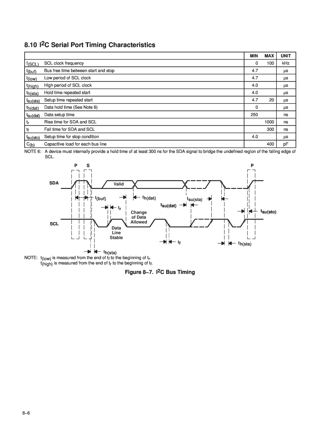
8.10 I2C Serial Port Timing Characteristics
Figure 8−7. I 2C Bus Timing
TAS3002
9 System Diagrams
Figure 9−1. Stereo Application
Clock
TAS3002
TAS3001
Figure 9−2. TAS3002 Device, 2.1 Channels
PLASTIC QUAD FLATPACK
10 Mechanical Information
PFB S-PQFP-G48
10−2
Top
Page
Image
Contents