www.ti.com
Programming the TMS320DM642
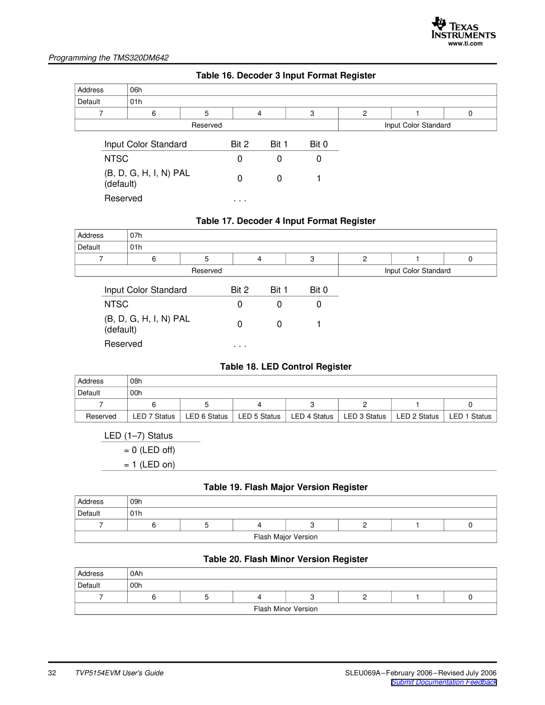
Table 16. Decoder 3 Input Format Register
Address | 06h |
|
|
|
|
|
|
Default | 01h |
|
|
|
|
|
|
7 | 6 | 5 | 4 | 3 | 2 | 1 | 0 |
|
| Reserved |
|
|
| Input Color | Standard |
Input Color Standard
NTSC
(B, D, G, H, I, N) PAL (default)
Reserved
Bit 2 | Bit 1 | Bit 0 |
0 | 0 | 0 |
0 | 0 | 1 |
. . . |
|
|
Table 17. Decoder 4 Input Format Register
Address | 07h |
|
|
|
|
|
|
Default | 01h |
|
|
|
|
|
|
7 | 6 | 5 | 4 | 3 | 2 | 1 | 0 |
|
| Reserved |
|
|
| Input Color | Standard |
Input Color Standard
NTSC
(B, D, G, H, I, N) PAL (default)
Reserved
Bit 2 | Bit 1 | Bit 0 |
0 | 0 | 0 |
0 | 0 | 1 |
. . . |
|
|
Table 18. LED Control Register
Address | 08h |
|
|
|
|
|
|
Default | 00h |
|
|
|
|
|
|
7 | 6 | 5 | 4 | 3 | 2 | 1 | 0 |
Reserved | LED 7 Status | LED 6 Status | LED 5 Status | LED 4 Status | LED 3 Status | LED 2 Status | LED 1 Status |
LED
=0 (LED off)
=1 (LED on)
Table 19. Flash Major Version Register
Address | 09h |
|
|
|
|
|
|
Default | 01h |
|
|
|
|
|
|
7 | 6 | 5 | 4 | 3 | 2 | 1 | 0 |
|
|
| Flash Major Version |
|
|
| |
Table 20. Flash Minor Version Register
Address | 0Ah |
|
|
|
|
|
|
Default | 00h |
|
|
|
|
|
|
7 | 6 | 5 | 4 | 3 | 2 | 1 | 0 |
|
|
| Flash Minor Version |
|
|
| |
32 | TVP5154EVM User's Guide | SLEU069A |
|
| Submit Documentation Feedback |
