All installations and services must be performed by qualified service personnel.
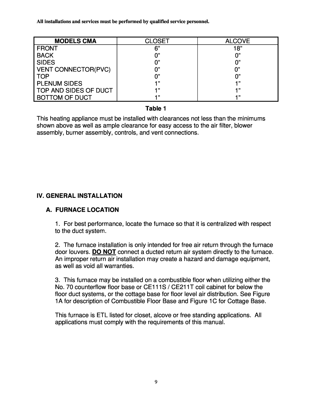
MODELS CMA | CLOSET | ALCOVE |
FRONT | 6” | 18” |
BACK | 0” | 0” |
SIDES | 0” | 0” |
VENT CONNECTOR(PVC) | 0” | 0” |
TOP | 0” | 0” |
PLENUM SIDES | 1” | 1” |
TOP AND SIDES OF DUCT | 1” | 1” |
BOTTOM OF DUCT | 1” | 1” |
Table 1
This heating appliance must be installed with clearances not less than the minimums shown above as well as ample clearance for easy access to the air filter, blower assembly, burner assembly, controls, and vent connections.
IV. GENERAL INSTALLATION
A.FURNACE LOCATION
1.For best performance, locate the furnace so that it is centralized with respect to the duct system.
2.The furnace installation is only intended for free air return through the furnace door louvers. DO NOT connect a ducted return air system directly to the furnace. An improper return air installation may create a hazard and damage equipment, as well as void all warranties.
3.This furnace may be installed on a combustible floor when utilizing either the No. 70 counterflow floor base or CE111S / CE211T coil cabinet for below the floor duct systems, or the cottage base for floor level air distribution. See Figure 1A for description of Combustible Floor Base and Figure 1C for Cottage Base.
This furnace is ETL listed for closet, alcove or free standing applications. All applications must comply with the requirements of this manual.
9