All installations and services must be performed by qualified service personnel.
G. CONNECTING THE EXHAUST VENT AND COMBUSTION AIR INTAKE
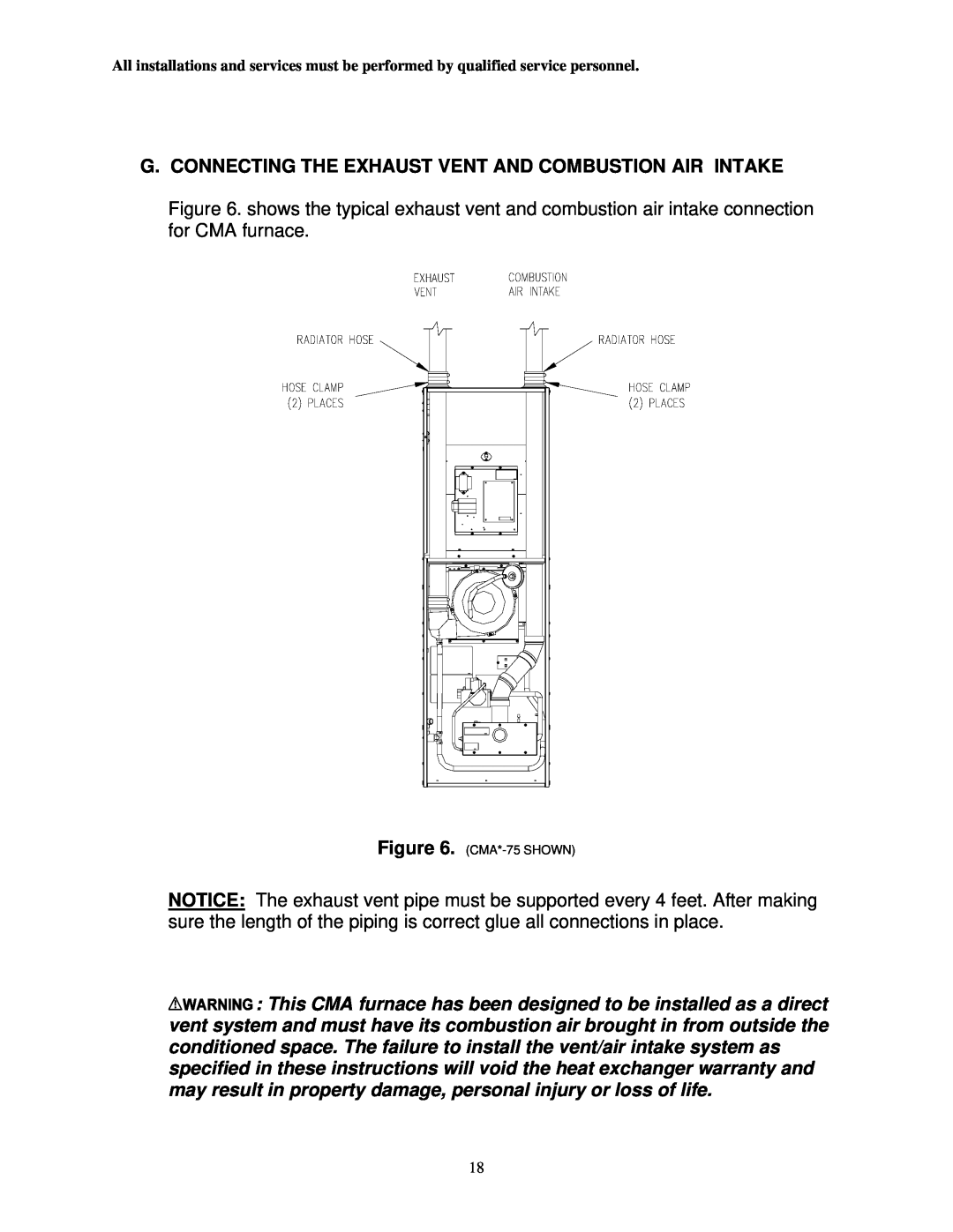
Figure 6. shows the typical exhaust vent and combustion air intake connection for CMA furnace.
Figure 6. (CMA*-75 SHOWN)
NOTICE: The exhaust vent pipe must be supported every 4 feet. After making sure the length of the piping is correct glue all connections in place.
![]()
![]()
![]()
![]()
![]()
![]()
![]()
![]()
![]()
![]()
![]()
![]()
![]()
![]()
![]()
![]()
![]() : This CMA furnace has been designed to be installed as a direct vent system and must have its combustion air brought in from outside the conditioned space. The failure to install the vent/air intake system as specified in these instructions will void the heat exchanger warranty and may result in property damage, personal injury or loss of life.
: This CMA furnace has been designed to be installed as a direct vent system and must have its combustion air brought in from outside the conditioned space. The failure to install the vent/air intake system as specified in these instructions will void the heat exchanger warranty and may result in property damage, personal injury or loss of life.
18