All installations and services must be performed by qualified service personnel.
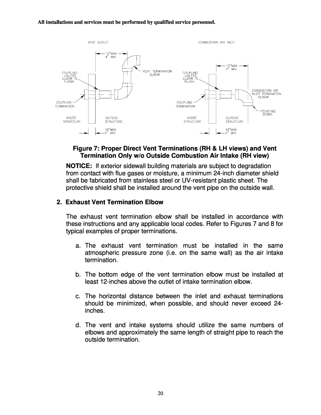
Figure 7: Proper Direct Vent Terminations (RH & LH views) and Vent
Termination Only w/o Outside Combustion Air Intake (RH view)
NOTICE: If exterior sidewall building materials are subject to degradation from contact with flue gases or moisture, a minimum
2. Exhaust Vent Termination Elbow
The exhaust vent termination elbow shall be installed in accordance with these instructions and any applicable local codes. Refer to Figures 7 and 8 for typical examples of proper terminations.
a. The exhaust vent termination must be installed in the same atmospheric pressure zone (i.e. on the same wall) as the air intake termination.
b.The bottom edge of the vent termination elbow must be installed at least
c.The horizontal distance between the inlet and exhaust terminations should be minimized, when possible, and should never exceed 24- inches.
d.The vent and intake systems should utilize the same numbers of elbows and approximately the same length of straight pipe to reach the outside termination.
20