All installations and services must be performed by qualified service personnel.
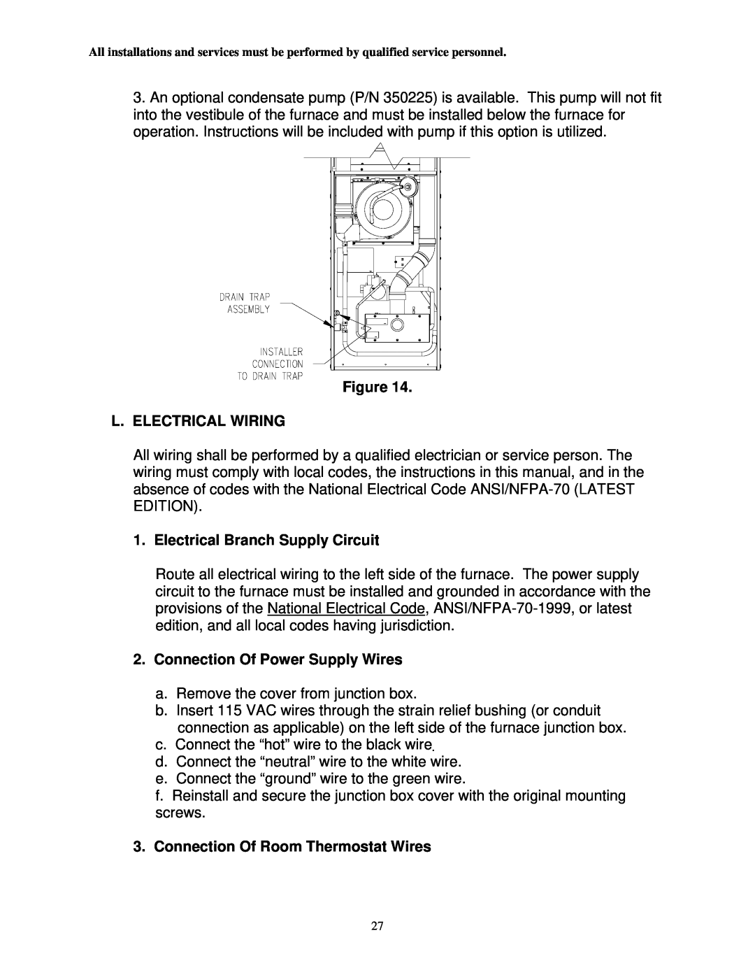
3.An optional condensate pump (P/N 350225) is available. This pump will not fit into the vestibule of the furnace and must be installed below the furnace for operation. Instructions will be included with pump if this option is utilized.
Figure 14.
L.ELECTRICAL WIRING
All wiring shall be performed by a qualified electrician or service person. The wiring must comply with local codes, the instructions in this manual, and in the absence of codes with the National Electrical Code
1. Electrical Branch Supply Circuit
Route all electrical wiring to the left side of the furnace. The power supply circuit to the furnace must be installed and grounded in accordance with the provisions of the National Electrical Code,
2.Connection Of Power Supply Wires
a.Remove the cover from junction box.
b.Insert 115 VAC wires through the strain relief bushing (or conduit connection as applicable) on the left side of the furnace junction box.
c.Connect the “hot” wire to the black wire.
d.Connect the “neutral” wire to the white wire.
e.Connect the “ground” wire to the green wire.
f.Reinstall and secure the junction box cover with the original mounting screws.
3.Connection Of Room Thermostat Wires
27