Thermo Products CMA2-75N, CMA1-50N service manual Figure K.CONDENSATE DRAIN LINE AND TRAP ASSEMBLY

Models: CMA1-50N CMA2-75N

1 55
Download 55 pages 9.18 Kb
Page 28
Image 28
Figure 13.

All installations and services must be performed by qualified service personnel.

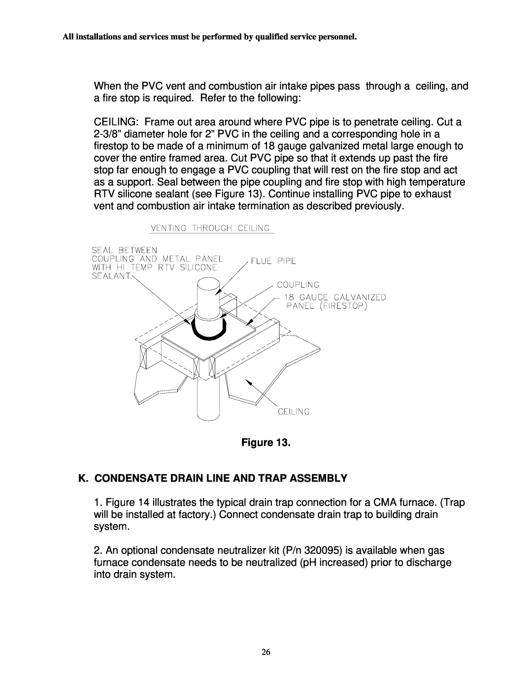
When the PVC vent and combustion air intake pipes pass through a ceiling, and a fire stop is required. Refer to the following:

CEILING: Frame out area around where PVC pipe is to penetrate ceiling. Cut a 2-3/8” diameter hole for 2” PVC in the ceiling and a corresponding hole in a firestop to be made of a minimum of 18 gauge galvanized metal large enough to cover the entire framed area. Cut PVC pipe so that it extends up past the fire stop far enough to engage a PVC coupling that will rest on the fire stop and act as a support. Seal between the pipe coupling and fire stop with high temperature RTV silicone sealant (see Figure 13). Continue installing PVC pipe to exhaust vent and combustion air intake termination as described previously.

Figure 13.

K.CONDENSATE DRAIN LINE AND TRAP ASSEMBLY

1.Figure 14 illustrates the typical drain trap connection for a CMA furnace. (Trap will be installed at factory.) Connect condensate drain trap to building drain system.

2.An optional condensate neutralizer kit (P/n 320095) is available when gas furnace condensate needs to be neutralized (pH increased) prior to discharge into drain system.

26

Page 28
Image 28
Thermo Products CMA2-75N, CMA1-50N service manual Figure K.CONDENSATE DRAIN LINE AND TRAP ASSEMBLY