Split Type
Contents
Troubleshooting
Indoort Unit
Original instruction
Work undertaken Protective gear worn
Explanation of indications
Explanation of illustrated marks
Indication Explanation
Confirmation of warning label on the main unit
Description
Precaution for Safety
Proceeding with the repair work
Refrigerant used by this air conditioner is the R410A
Resistance and water drainage
Explanations given to user
Relocation
Declaration of Conformity
Specifications
Flare nut
Safety Caution Concerned to New Refrigerant
Copper pipe Piping
Joint
Tools
General tools Conventional tools can be used
Concealed Duct type
SM56 type Round duct
SM110 type Round duct
Space required for Installation and servicing
RAV-SM404MUT∗, RAV-SM454MUT∗, RAV-SM564MUT∗
Dimension
RAV-SM564BT∗, RAV-SM804BT∗, RAV-SM1104BT∗, RAV-SM1404BT∗
RAV-SM564CT∗, RAV-SM804CT∗, RAV-SM1104CT∗, RAV-SM1404CT∗
Compact 4-way Cassette Type
RAV-SM564BT ∗, RAV-SM804BT ∗, RAV-SM1104BT ∗, RAV-SM1404BT ∗
Ceiling Type
RAV-SM564CT ∗, RAV-SM804CT ∗, RAV-SM1104CT ∗, RAV-SM1404CT ∗
Specifications of Electrical Parts
Parts name Type Specifications
Indoor Controller Block Diagram
Case of Connection of Wired Simple Remote Controller
Case of Connection of Wireless Remote Controller
Wireless remote controller
Max units
Outline of specifications Remarks
Control outline Command
Temperature in heating
Heat
Outline of specifications
Ceiling type
Tc n
Tcj
Tcn
Conditions
Setup at shipment
Cooling/dry operation Heating/fan operation
All operations
Alarm
All modes
Case of wired remote controller
LCD
Figure if To 28C
Setup AT Local
Outline of specifications Remarks
MCC-1402
TCJ Exct Disp CHK
Indoor P.C. Board Optional Connector Specifications MCC-1402
Troubleshooting procedure
Summary of Troubleshooting
Before troubleshooting
Wired remote controller type
Wireless remote controller type
Outline of judgment
Lamp indication Check code Cause of trouble occurrence
Lamp indication Check code
Others Other than Check Code
Remote controller detected
Indoor unit detected
Central control devices detected
Check Code List
Error mode detected by indoor unit
Error mode detected by outdoor unit
Air conditioner
Operation of diagnostic function Check Status
Power supply error of remote controller, Indoor
Check code E01 error
E09 error
E04 error
E10 error
E18 error
E08, L03, L07, L08 error
L09 error
L20 error
L30 error
P30 error Central controller
P10 error
F10 error
P12 error
Exchange to cooling cycle
P19 error
Check by tester
Exchange to heating cycle
F02 error
F01 error
C06 error 11 model connection interface
E03 error Master indoor unit
F29 error
P31 error Follower indoor unit
TA, TC, TCJ, TE,TS, to sensor
Temperature Resistance value characteristic table
TA, TC, TCJ, TE, TS, to sensor
TD, TL sensor
Part name Checking procedure
Position Resistance value
Replacement procedures
Case
Setting data read out from Eeprom
C. Board for indoor unit servicing replacement procedures
Code No. required at least Contents
Writing the setting data to Eeprom
MCC-1402
Setting data Type
Setting data Factory-set value
Setting data Type Type name abb
Type Code No
Test Run Setup on Remote Controller Wired remote controller
Compact 4-way Cassette Type and Concealed Duct Type
Procedure Description
Test cooling operation Test heating operation
Practical operation
LED Display on Indoor P.C. Board D002 Red
D203 Red
To change the selected indoor unit, proceed to Procedure
Function Selection Setup
Using the set temperature
To change item to be set up, proceed to Procedure
Item No. DN table Selection of function
Description At shipment
Description At shipment
When connected 2 remote controllers operate the twin
Wireless remote controller
When connected 2 remote controllers operate an idoor unit
Setup method
Contents
Group control operation
Calling of error history Contents
Pushing Test button returns the display to usual display
System example
Indoor unit power-ON sequence
Initial communication
Usual regular communication
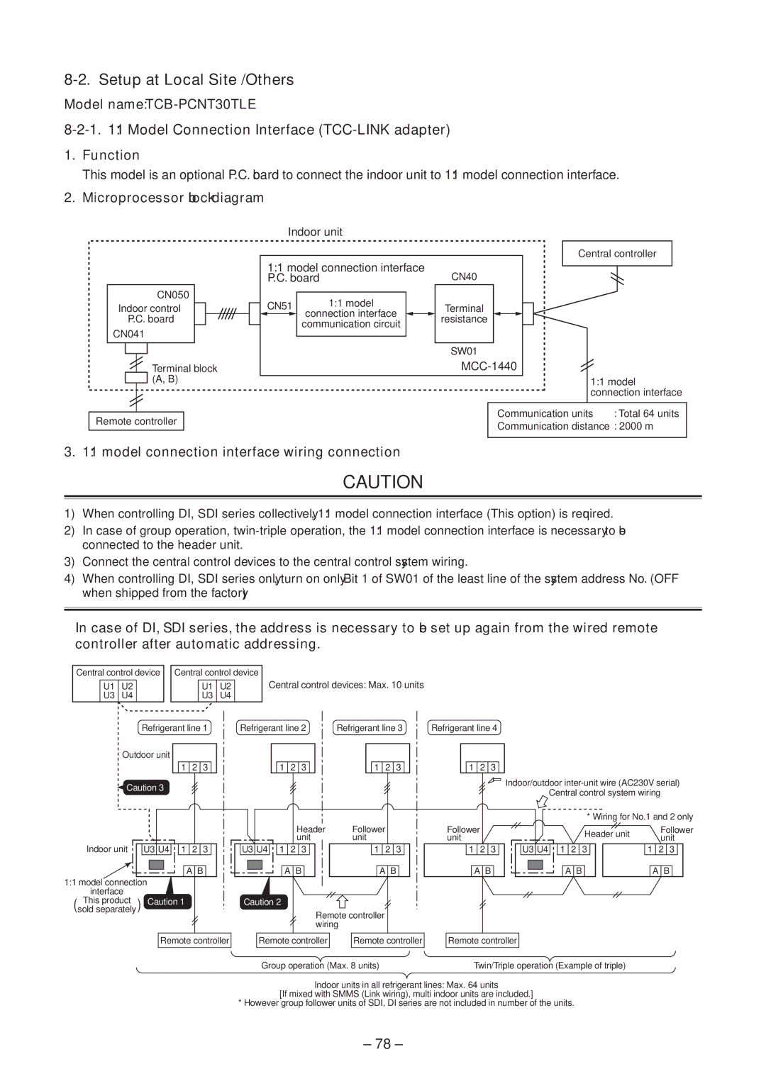
Model Connection Interface TCC-LINK adapter
Microprocessor block diagram
Model connection interface wiring connection
Model name TCB-PCNT30TLE
Wiring Specifications
C. Board Switch SW01 Setup
Address setup
How to set up from indoor unit side by remote controller
External view of P.C. board assembly
Push Test + Vent buttons for 4 seconds or more
During unset time, At shipment from factory is displayed
Address Setup
Address setup procedure
System configuration
Address Setup & Group Control Terminology
Example
Automatic Address Example from Unset Address No miswiring
Only turning on source power supply Automatic completion
Simultaneously for 4 seconds or more
Using timer time Buttons, set the line address
Push SET + CL + Test buttons
Button
Procedure
To know the position of indoor unit body by address
Button if the unit stops
Detachment
Part name Procedure
Ceiling panel RBC-UM11PGWE Preparing work
Attachment
Part name Procedure Remarks
Part name Procedure Remarks Ceiling panel
Panel has directionality
Procedure Remarks
No. Part name
Electric parts box
No. Part name Procedure
Fan motor 1. Detachment
Drain pan 1. Detachment
Drain pump 1. Detachment
Part name Procedure Remarks Heat
Exchanger Recover refrigerant gas
Details of sensor lead wire drawing
Part name Procedure Remarks
RAV-SM∗∗∗BT ∗
Fan motor Remove the Multi blade fan
† Drain pump Remove the drain pan and float switch
No. Part name Procedure Remarks
100
101
102
103
209
104
105
Location Description Model name
404MUT-E 454MUT-E 564MUT-E
106
404MUT-TR 454MUT-TR 564MUT-TR
107
Electric parts
401
Location Model name
108
109
RAV-SM564BT-E RAV-SM564BT-TR
110
111
RAV-SM804BT-E RAV-SM804BT-TR
112
113
1104BT-TR
114
Location Model name RAV-SM Description
564BT-E 804BT-E 1104BT-E 1404BT-E
264
220
115
116
Description Model name RAV-SM
Location
117
118
Description 564CT-E 804CT-E 1104CT-E 1404CT-E
Check of Concentration Limit
Toshiba Carrier Corporation