4 Replacement Procedures | 4.21 VGA PCB |
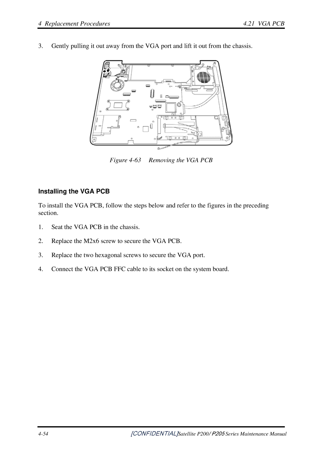
3.Gently pulling it out away from the VGA port and lift it out from the chassis.
Figure 4-63 Removing the VGA PCB
Installing the VGA PCB
To install the VGA PCB, follow the steps below and refer to the figures in the preceding section.
1.Seat the VGA PCB in the chassis.
2.Replace the M2x6 screw to secure the VGA PCB.
3.Replace the two hexagonal screws to secure the VGA port.
4.Connect the VGA PCB FFC cable to its socket on the system board.
[CONFIDENTIAL]Satellite P200/ P205 Series Maintenance Manual |