| 4 Replacement Procedures | |
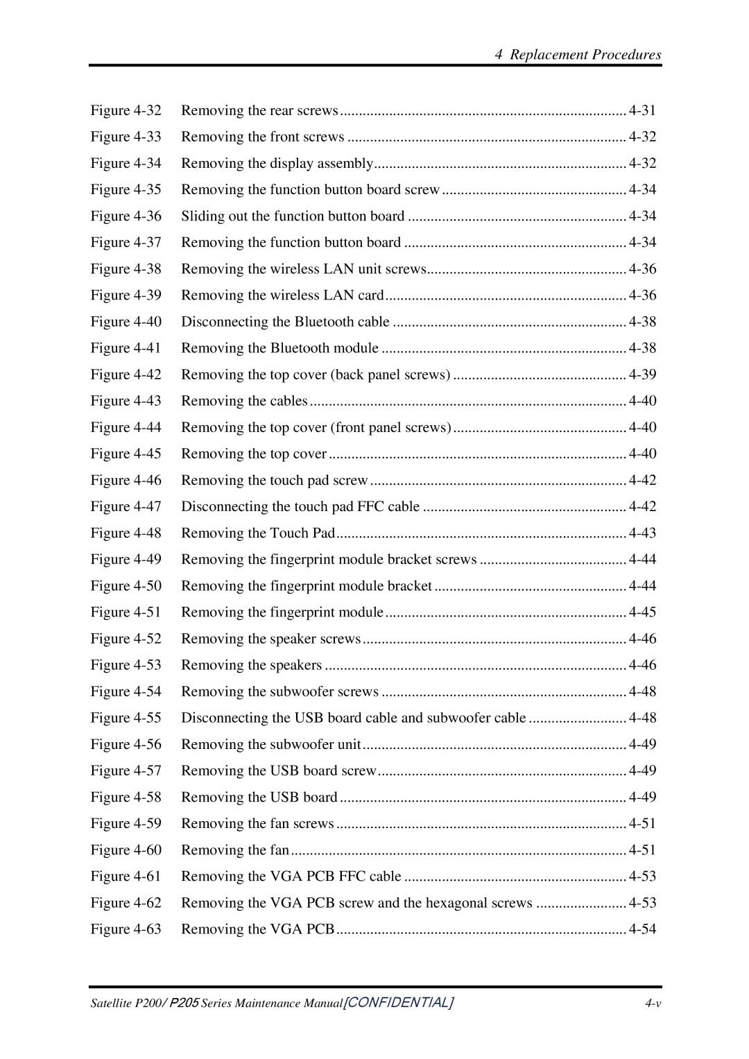
Figure | Removing the rear screws | |
Figure | Removing the front screws | |
Figure | Removing the display assembly | |
Figure | Removing the function button board screw | |
Figure | Sliding out the function button board | |
Figure | Removing the function button board | |
Figure | Removing the wireless LAN unit screws | |
Figure | Removing the wireless LAN card | |
Figure | Disconnecting the Bluetooth cable | |
Figure | Removing the Bluetooth module | |
Figure | Removing the top cover (back panel screws) | |
Figure | Removing the cables | |
Figure | Removing the top cover (front panel screws) | |
Figure | Removing the top cover | |
Figure | Removing the touch pad screw | |
Figure | Disconnecting the touch pad FFC cable | |
Figure | Removing the Touch Pad | |
Figure | Removing the fingerprint module bracket screws | |
Figure | Removing the fingerprint module bracket | |
Figure | Removing the fingerprint module | |
Figure | Removing the speaker screws | |
Figure | Removing the speakers | |
Figure | Removing the subwoofer screws | |
Figure | Disconnecting the USB board cable and subwoofer cable | |
Figure | Removing the subwoofer unit | |
Figure | Removing the USB board screw | |
Figure | Removing the USB board | |
Figure | Removing the fan screws | |
Figure | Removing the fan | |
Figure | Removing the VGA PCB FFC cable | |
Figure | Removing the VGA PCB screw and the hexagonal screws | |
Figure | Removing the VGA PCB | |
Satellite P200/ P205 Series Maintenance Manual[CONFIDENTIAL] |
