INSTALLATION MANUAL To Personnel Charged in Installation (Electric) Work and Service

Program Weekly Timer

MODEL : RBC-EXW21E

Accessory parts

Part Name

Q’ty

Program weekly timer

1


Connecting cable

1

(Length: 1.2m)

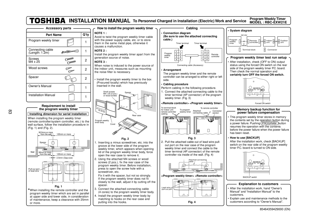
How to install the program weekly timer

NOTE 1 :

Avoid to twist the program weekly timer cable with the power supply cable, etc. or to store them in the same metal pipe, otherwise it causes a malfunction.

NOTE 2 :

Cabling

Connection diagram

(Be sure to use the attached connecting cable.)

Timer terminal Timer terminal

1

1

1

1

• System diagram

DC12V

Program


Remote


weekly


controller


timer


4


wires


: Terminal block


Indoor unit

: Connector

Outdoor unit

83

Screws

2

M4 x 25


Wood screws

2


Spacer

2


Owner’s Manual

1


Installation Manual

1


Requirement to install

the program weekly timer

Installing dimension for serial installation

When installing the program weekly timer (remote controller/system controller, etc.) to the wall surface, follow the installation procedure in (Fig. 1) and (Fig. 2).


92.5mm or more

125mm or more


from the wall


Spacer


Wall

90mm or more

125mm or more


from the wall

2.5mm (Gap size)

Pull-out port of lead wire

Fig. 1

*When installing the remote controller and the program weekly timer which are set in parallel at upper side and lower side, in consideration of maintenance, keep a clearance with 25mm or more.

Install the program weekly timer apart from the generation source of noise.

NOTE 3 :

When noise is induced to the power source of the indoor unit, measures such as mounting the noise filter is necessary.

Install the program weekly timer to the box (Procured locally) which has previously inserted in the wall.

Small screws

Spacer

M4 x 25 (2 pcs.)


or wood screws


Rear case

Program weekly

timer body

Cover

Fig. 2

1.Inserting a minus screwdriver, etc. into the groove at the lower side of the program weekly timer, which appears when opening lid of the program weekly timer body, force open the rear case to remove it.

2.Using the attached M4 screws or wood screws (2 pcs.), fix the rear case of the program weekly timer. Before installation, press to open the screw hole with a screwdriver, etc.

Fix it with the spacer, but not so strongly. If the program weekly timer does not fit closely to the wall, adjust it by cutting off the spacer.

3.Connect the attached connecting cable

(4 cores) to the program weekly timer body.

4.Install the program weekly timer body by matching to hooks on the rear case and putting into the hooks.

Program

2

2


2

2

Remote

weekly

3

3


3

3

controller

timer


4

4

4

4


Connecting cable (Accessory)

Arrangement

The program weekly timer and the remote controller can be arranged to either right or left side.

Cabling procedure

Perform cabling in the following procedure.

1.Connect the attached connecting cable to the timer terminal (4P connector) of the program weekly timer. (Fig. 3)

<Remote controller> <Program weekly timer>

To terminal block

To program

To remote controller

for indoor unit

Attached

Connector

remote controller

weekly timer

connecting cable

section

cabling


Fig. 3

2.Pull the attached cable out of lead wire pull- out port on the rear case of the program weekly timer and connect the cable to the timer terminal (4P connector) of the remote controller via inside of the wall. (Fig. 4)

Attached connecting cable

<Program weekly timer> <Remote controller>

Lead wire pull-out port

Fig. 4

Program weekly timer test run setup

After installation, check (OFF to ON) output status using the forced ON switch on the rear side of the program weekly timer P.C. board. Then check the normal operation and certainly turn OFF the forced ON switch.

ON OFF

ON OFF

Forced ON switch

Memory backup function for power failure compensation

This program weekly timer stores in memory the contents set by the operation button during a power failure. Pushing PROGRAM button resumes the operation with the contents before the power failure when the power failure has been reset.

How to use [BACKUP]

After the installation work, check [BACKUP] switch on the rear side of the program weekly timer P.C. board is turned to ON side.

ON OFF

ON OFF

BACKUP switch

Explanation to customers

After the installation work, hand “Owner’s Manual” and “Installation Manual” to the customers.

Explain use and maintenance methods to the customers according to “Owner’s Manual”.

85464359429000 (EN)

Page 83
Image 83
Toshiba R410A Accessory parts Part Name ’ty, How to install the program weekly timer, Cabling, Explanation to customers

R410A specifications

Toshiba R410A is a highly regarded refrigerant known for its efficiency and environmental benefits. This hydrofluorocarbon (HFC) mixture is widely used in various air conditioning and refrigeration applications due to its excellent thermodynamic properties. One of the standout features of R410A is its superior energy efficiency, which contributes to lower energy consumption and reduced CO2 emissions in HVAC systems.

One significant advantage of R410A over older refrigerants, such as R22, is its lower ozone depletion potential (ODP). R410A has an ODP of zero, making it a more environmentally friendly choice. This characteristic aligns with global initiatives aimed at protecting the ozone layer and promoting sustainable practices. The shift to R410A has been supported by government regulations in many countries, phasing out older, more harmful refrigerants.

Toshiba has incorporated advanced technologies in its R410A compatible products, enhancing performance and reliability. Among these technologies is the inverter technology that allows the compressor to operate at variable speeds. This functionality leads to improved temperature regulation, reduced noise levels, and further energy savings. Inverter systems provide precise control over the cooling and heating processes, allowing for a comfortable indoor environment while minimizing wastage of energy.

R410A also exhibits excellent heat transfer properties, which boosts cooling capacity. This feature makes it suitable for large-scale HVAC systems, including commercial and industrial applications. Its high-pressure characteristics enable the design of more compact and efficient components, allowing for smaller units and easier installation.

Furthermore, Toshiba's dedication to technological innovation is visible in its commitment to research and development. The company continuously strives to optimize systems that utilize R410A, focusing on reliability and longevity. This includes improved compressor designs, enhanced heat exchangers, and the integration of smart controls that adapt to the varying load conditions in real-time.

In terms of safety, R410A is classified as non-toxic and non-flammable under normal conditions, making it a safe choice for use in residential and commercial settings. However, it is important to note that R410A operates at higher pressures compared to traditional refrigerants, necessitating proper equipment design and handling procedures.

In conclusion, Toshiba R410A stands out in the market for its energy efficiency, environmental safety, and technological advancements. It is an ideal refrigerant for modern HVAC applications, contributing to both comfort and sustainability. As the industry continues to evolve, R410A remains a pivotal element in the quest for responsible and efficient refrigeration solutions.