Toshiba R410A Standard Remote Controller, How to perform cabling of the remote controller, Q’ty

Models: R410A

1 88
Download 88 pages 10.91 Kb
Page 81
Image 81
Standard Remote Controller

INSTALLATION MANUAL To Personnel Charged in Installation (Electric) Work and Service

Standard Remote Controller

MODEL : RBC-AMT21E

Accessory parts

Part Name

Q’ty

Part Name

Q’ty

Remote controller


Spacer


(200mm-cable

1


2


attached)


Screw


Wire joint


M4 x 25

2


2

Wood screw


Installation


2

Manual

1

How to install remote controller

NOTE 1 : Avoid to twist the remote controller cable with power supply cable, etc. or to store them in the same metal pipe, otherwise it causes a malfunction.

NOTE 2 : Install the remote controller apart from the generation source of noise.

NOTE 3 : When noise is contained to the unit power supply, counter measures such as mounting the noise filter is necessary.

When using the remote controller as exposed, install it at the wall surface where it can be fixed.

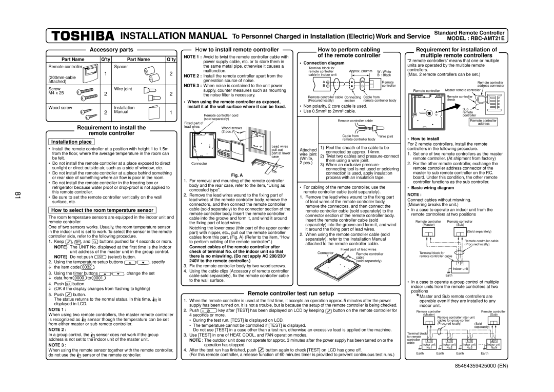
How to perform cabling of the remote controller

• Connection diagram

Terminal block for

Approx. 200mm


remote controller

W : White

cable in indoor unit


B : Black

A

W

Remote

B


B

controller

Remote controller cable Connecting

Cable from

(Procured locally)

section

remote controller body

Non polarity, 2 core cable is used.

Use 0.5mm² to 2mm² cable.

Requirement for installation of

multiple remote controllers

“2 remote controllers” means that one or multiple units are operated by the multiple remote controllers.

(Max. 2 remote controllers can be set.)

Remote controller address connector

Remote controller Master remote controller Part Name

Remote controller check Q’ty

Sub How to perform cabling of the remote controller remote

Requirement to install the

remote controller

Installation place

Install the remote controller at a position with height 1 to 1.5m


from the floor, where the average temperature in the room can


be felt.

Do not install the remote controller at a place exposed to direct


sunlight or direct outside air, such as a side of window, etc.

Do not install the remote controller at a place behind something


or rear side of something where air flow is poor in the room.

Remote controller cord (sold separately)

Fixed part of

lead wiresWood screws (2 pcs.)• Connection diagramInstallation place

Connector

Fig. A

Lead wires pull-out part at lower case


Remote controller cable


Cable from


Wire joint


remote controller body


Attached

1)

Peel the sheath of the cable to be

wire joint


connected by approx. 14mm.

2)

Twist two cables and pressure-connect

(White,


them using a wire joint.


2 pcs.)


3)

When an exclusive pressure-


connecting tool is not used or soldering


connection is used, apply insulation


process with an insulation tape.

controller

Remote controller address

• How to install

For 2 remote controllers, install the remote controllers in the following procedure.

1.

Set one of two remote controllers as the master


remote controller. (At shipment from factory)

2.

For the other remote controller, exchange the


remote controller address connector of the


master to sub remote controller on the P.C.


board. Under this condition, the other remote

81

Do not install the remote controller in the freezing box or


refrigerator because water proof or drop-proof is not applied to


this remote controller.

Be sure to set the remote controller vertically on the wall


surface, etc.

How to select the room temperature sensor

The room temperature sensors are equipped in the indoor unit and remote controller.

One of two sensors works. Usually, the room temperature sensor in the indoor unit is set to work. To select the sensor in the remote controller side, refer to the following procedure.

1.

Keep

, SET , and

CL buttons pushed for 4 seconds or more.


NOTE) The UNIT No. displayed at the first time is the indoor


unit address of the master unit in the group control.


NOTE) Do not push

UNIT

(select) button.


2.

Using the temperature setup buttons

/

, specify


the item code 0032 .


3.

Using the timer buttons

/

, change the set


data from

0000 to

0001 .


4.

Push

SET

button.


(OK if the display changes from flashing to lighting)

1.For removal and mounting of the remote controller body and the rear case, refer to the item, “Using as concealed type”.

2.Remove the lead wires wound to the fixing part of lead wires of the remote controller body, remove the connectors, and then connect the remote controller cable (sold separately) to the connector section of the remote controller body. Insert the remote controller cable into the groove and form it, and wind it around the fixing part of lead wires.

Notching the lower case (thin part of the upper center part) with nipper, etc., pull out the remote controller cables from this part. (Fig. A) (Refer to the item, “How to perform cabling of the remote controller”.)

Connect cables of the remote controller after check of terminal No. of the indoor unit so that there is no miswiring. (Do not apply AC 200/230/ 240V to the remote controller.)

3.Fix the remote controller body by two wood screws.

4.Using the cable clips (Accessory of remote controller cable sold separately), fix the remote controller cable to the wall surface.

For cabling of the remote controller, use the remote controller cable (sold separately).

1.Remove the lead wires wound to the fixing part of lead wires of the remote controller body, remove the connectors, and then connect the remote controller cable (sold separately) to the connector section of the remote controller body. Insert the remote controller cable (sold separately) into the groove and form it, and wind it around the fixing part of lead wires.

2.When using the remote controller cable (sold separately), refer to the Installation Manual attached to the remote controller cable.

Connector

Fixed part of lead wires

Remote controller


cable


(sold separately)

controller functions as the sub controller.

• Basic wiring diagram

NOTE :

Connect cables without miswiring. (Miswiring breaks the unit.)

In a case to operate an indoor unit from the remote controllers at two positions

Remote controller

Remote controller


(Master)


(Sub)


(Sold separately)


Remote controller cable


(Procured locally)

Terminal block for remote controller cable

1 Fig. A 2

• How to install Indoor unit

Earth

• In a case to operate a group control of multiple

indoor units from the remote controllers at two

positions

5.Push How to select the room temperature sensor button.

The status returns to the normal status. In this time, • Basic wiring diagram is displayed in LCD.

NOTE 1 :

When using two remote controllers, the master remote controller is recognized as Manual background sensor though the temperature can be set from either master or sub remote controller.

NOTE 2 :

In a group control, the Manual background sensor does not work if the group address is not set to the indoor unit of the master unit.

NOTE 3 :

When using the remote sensor together with the remote controller, do not use the Manual background sensor of the remote controller.

Remote controller test run setup

1.When the remote controller is used at the first time, it accepts an operation approx. 5 minutes after the power supply has been turned on. It is not a trouble, but is because the setup of the remote controller is being checked.

2.Push Manual background key after [TEST] has been displayed on LCD by keeping Manual background button on the remote controller for 4 seconds or more.

During the test run, [TEST] is displayed on LCD.

The temperature cannot be controlled if [TEST] is displayed.

Do not use [TEST] in a case other than a test run, otherwise an excessive load is applied on the machine.

3.Use [TEST] in one of HEAT, COOL, and FAN operation modes.

NOTE : The outdoor unit does not operate for approx. 3 minutes after the power supply has been turned on or the operation has stopped.

4.After the test run has finished, push Manual background button again to check [TEST] on LCD has gone off.

(For this remote controller, a release function of 60 minutes timer is provided to prevent continuous test runs.)

Master and Sub remote controllers are

*operable even if they are installed to any

indoor unit.


Remote controller


Remote controller


(Master)

Remote controller inter-unit


(Sub)


cables for group control


(Procured locally)

(Sold


separately)

Terminal block


for remote


controller


cable


A

B


A

B


A

B


A

B


Indoor unit


Indoor unit


Indoor unit


Indoor unit


No.1


No.2


No.3


No.N


Earth

Earth

Earth


Earth

85464359425000 (EN)

Page 81
Image 81
Toshiba R410A Standard Remote Controller, How to perform cabling of the remote controller, Installation place, Part Name