Manuals
/
Toshiba
/
Household Appliance
/
Air Conditioner
Toshiba
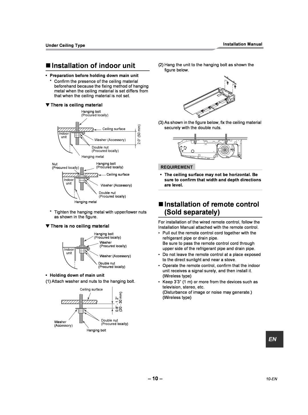
RAV-SP300CT-UL Installation of indoor unit, There is ceiling material, Requirement
Models:
RAV-SP360CT-UL
RAV-SP240CT-UL
RAV-SP180CT-UL
RAV-SP300CT-UL
RAV-SP420CT-UL
1
11
34
34
Download
34 pages
45.46 Kb
8
9
10
11
12
13
14
15
Troubleshooting
Install
„Wiring Diagram
Removing wire guard
Accessory Parts
Manual address setup procedure
Procedure
Remote control wiring
Precautions For Safety
Page 11
Image 11
Page 10
Page 12
Page 11
Image 11
Page 10
Page 12
Contents
English
AIR CONDITIONER SPLIT TYPE
RAV-SP180CT-UL RAV-SP240CT-UL RAV-SP300CT-UL
RAV-SP360CT-UL RAV-SP420CT-UL
ADOPTION OF NEW REFRIGERANT
Contents
Under Ceiling Type
1 ACCESSORY PARTS
„Accessory parts
Under Ceiling Type
2 PRECAUTIONS FOR SAFETY
Under Ceiling Type
Avoid installing in the following places
3 SELECTION OF INSTALLATION PLACE
„Installation space
„Height of ceiling
Under Ceiling TypeInstallation Manual
„Wireless remote control
„Before installation
2 Removing wire guard
5 Removal of protector
„External view
3 Removal of side panel
4 Removal of protective vinyl
Under Ceiling Type
Installation Manual Unit in mm
Using attached installation pattern
„Installation of hanging bolts
„Draw-outdirection of pipe/ wire
„Pipe knockout hole
There is ceiling material
„Installation of indoor unit
„Installation of remote control Sold separately
Installation Manual
„Permissible Piping Length and Height Difference
4 REFRIGERANT PIPING AND EVACUATING
„Refrigerant Piping
„Pipe size
Piping with outdoor unit
„Evacuation
Tightening connection
Refrigerant amount to be added
REQUIREMENT
Thermal insulation process
Under Ceiling Type
Under Ceiling Type
5 DRAIN PIPING WORK
„Piping/Heat insulating material
„Drain up
Under Ceiling Type
„Connection of drain hose
„Thermal insulating process
„Connection of drain pipe
Under Ceiling Type
6 ELECTRICAL CONNECTION
Remote control wiring
Wiring
Under Ceiling Type
REQUIREMENT
„Wire connection
Under Ceiling Type
19-EN
Connected at backside
Connected at upside
Under Ceiling Type
Single system
„System interconnection Wires and Ground Wire
„Remote Control Wiring
„Wiring Diagram
Procedure
„Changing applicable control setting
7 APPLICABLE CONTROLS
Procedure
Procedure
„Installation to high ceiling
„Using wireless remote control
1 → 2 → 3 → 4 → 5 →
Procedure example
„Filter sign setting
„To secure better effect of heating
„Group control
Procedure
Procedure
Procedure
Procedure
Procedure
Procedure
Procedure
Procedure
Under Ceiling Type
„Remote control switch monitoring function
Installation Manual
„Execute a test run
8 TEST RUN
2, 4 1,5
„Before test run
Procedure
Wireless remote control
Procedure
Procedure
Procedure
9 TROUBLESHOOTING
„Confirmation of error history
„Confirmation and check
30-EN
„Check codes and parts to be checked
Under Ceiling Type
31-EN
Under Ceiling Type
32-EN
Under Ceiling Type
EH99864801
Top
Page
Image
Contents