Under Ceiling Type
|
|
|
|
| 1.5” (39) |
|
|
|
|
|
|
| 2.0” (52) |
|
|
|
| Upper pipe |
| 8.5” (216) |
|
| |
|
|
|
|
| 8.3” (210) | ||
|
| Hole for remote control wires (knockout) |
|
|
| ||
|
|
| 4.3” (110) |
| |||
|
|
| Conduit hole |
|
| ||
|
|
|
| 3.0” (76) |
| ||
|
| (Hole for power supply cable. knockout) |
|
| |||
3.3” (84) |
|
| 4.1” (105) |
| |||
|
|
|
|
| |||
(170) | 12.6”(320) |
| 2.8” (70) | 2.1” (53) | (130) | 2.0”(50) | pipe)(Liquid(200)7.9” pipe)(Gas(216)8.5” |
6.7” | Left drain size | Refrigerant pipe | 5.1” | 26.8”(680) | |||
|
| (Liquid side ØC) |
|
| |||
|
|
|
|
| |||
|
|
|
|
|
| ||
|
| Refrigerant pipe (Gas side ØD) | Drain pipe |
| |||
|
|
|
|
|
| ||
|
|
|
|
| connecting |
| |
|
| B (Hanging position) |
| port |
|
| |
|
|
|
| 3.0” (75) | 3.8” (97) |
| |
|
|
|
|
| 5.7” (146) |
|
|
Installation Manual
Unit: in (mm)
6.6” (167)
Pipe
Drain port VP20
(Inner dia. Ø1.0” (26), hose attached)
(141) |
| 4.5” (114) |
| ||
5.6” |
|
|
Hanging bolt |
5.3” (135)
5.7” (145)
13.7” (347)
12.2” (311)
10.3” (262)
3.5” (90)
| Hole for remote control wires |
| |
|
| Conduit hole |
|
(32) | (92) | (knockout) |
|
| 3.3” (84) | ||
1.3” | 3.6” |
| |
| (171) | ||
|
|
| 6.7” |
Within 2.0” (50) | Ceiling surface |
Unit | |
|
|
| Pipe hole on wall |
| Hole for power supply cable |
|
| |||||||||||||||
|
| (Ø3.9” (100) hole) |
|
|
|
|
| Left drain pipe | |||||||||||||
|
|
|
|
|
| Outside air |
|
| |||||||||||||
|
|
|
|
|
| Knockout hole Ø3.6” (92)) |
|
| (knockout) | ||||||||||||
|
|
|
|
|
|
|
|
|
|
|
|
|
|
| Wireless sensor |
|
|
|
| ||
|
|
|
|
|
|
|
|
|
|
|
|
|
|
|
|
|
|
| |||
|
|
|
|
|
|
|
|
|
|
|
|
|
|
|
|
|
|
| |||
|
|
|
|
|
|
|
|
|
|
|
|
|
|
| mounting section |
|
|
|
| ||
A |
|
|
|
|
|
|
| ||||||||||||||
|
|
|
|
|
|
|
|
|
|
|
|
|
|
|
|
|
|
|
| Unit: in (mm) | |
|
|
|
|
|
|
|
|
|
|
|
|
|
|
|
| Model name |
| A | B | C | D |
|
|
|
|
|
|
|
|
|
|
|
|
|
|
|
|
|
|
|
|
|
|
|
|
|
|
|
|
|
|
|
|
|
|
|
|
|
| 180CT |
| 35.8” | 33.7” | Ø1/4” | Ø1/2” |
|
|
|
|
|
|
|
|
|
|
|
|
|
|
|
|
| (910) | (855) | (6.4) | (12.7) | |
|
|
|
|
|
|
|
|
|
|
|
|
|
|
|
|
|
| ||||
|
|
|
|
|
|
|
|
|
|
|
|
|
|
|
| 240CT |
| 46.5” | 44.3” |
|
|
|
|
|
|
|
|
|
|
|
|
|
|
|
|
|
|
|
|
| |||
|
|
|
|
|
|
|
|
|
|
|
|
|
|
|
|
|
|
| |||
|
|
|
|
|
|
|
|
|
|
|
|
|
|
|
|
| (1180) | (1125) | Ø3/8” | Ø5/8” | |
|
|
|
|
|
|
|
|
|
|
|
|
|
|
|
|
|
| ||||
|
|
|
|
|
|
|
|
|
|
|
|
|
|
|
|
|
|
|
| (9.5) | (15.9) |
|
|
|
|
|
|
|
|
|
|
|
|
|
|
|
| 300CT, 360CT |
| 62.8” | 60.6” | ||
|
|
|
|
|
|
|
|
|
|
|
|
|
|
|
| to 420CT |
| (1595) | (1540) |
|
|
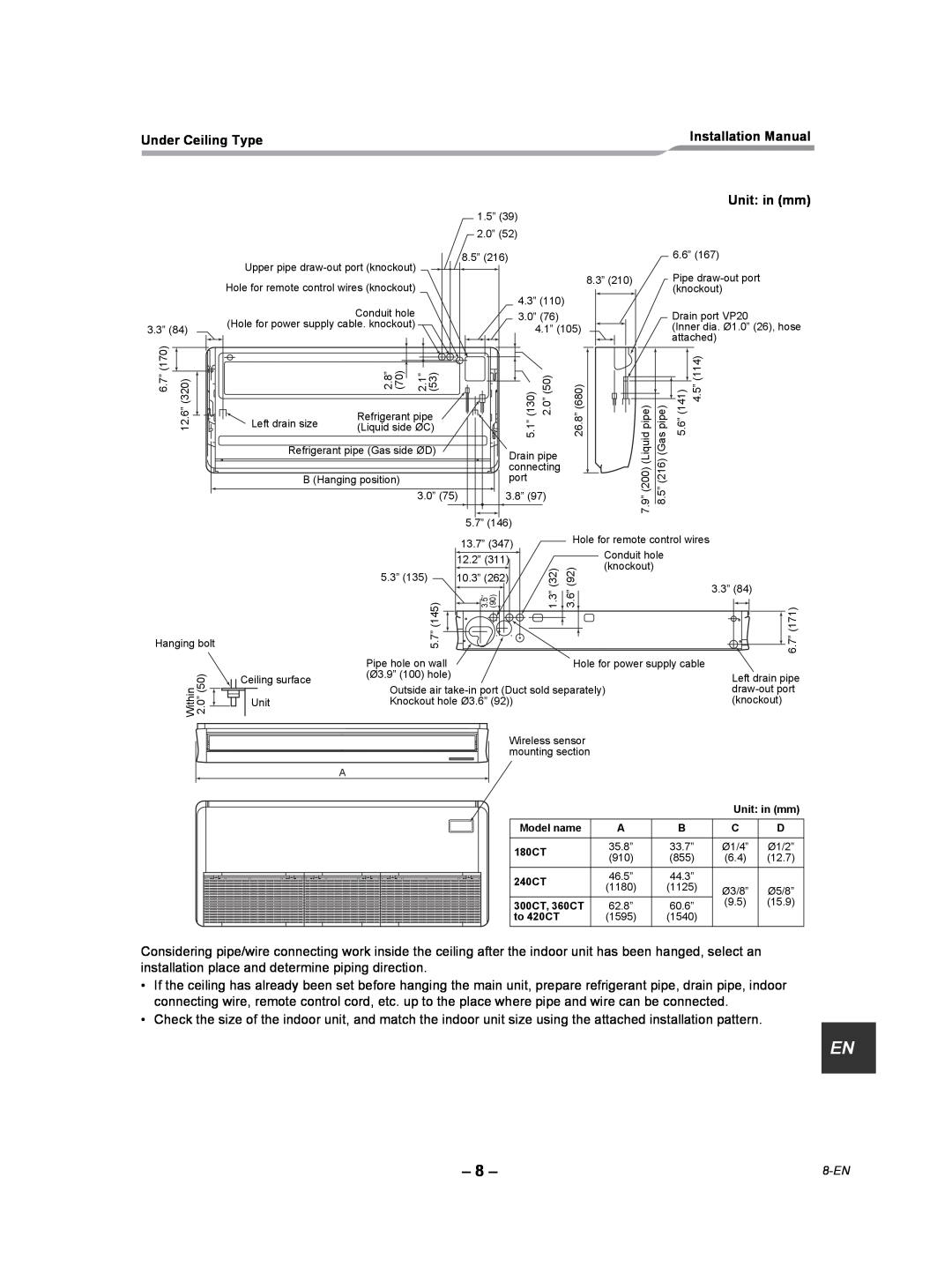
Considering pipe/wire connecting work inside the ceiling after the indoor unit has been hanged, select an installation place and determine piping direction.
•If the ceiling has already been set before hanging the main unit, prepare refrigerant pipe, drain pipe, indoor connecting wire, remote control cord, etc. up to the place where pipe and wire can be connected.
•Check the size of the indoor unit, and match the indoor unit size using the attached installation pattern.
EN |
– 8 – |