Under Ceiling Type | Installation Manual |
System interconnection Wires and Ground Wire
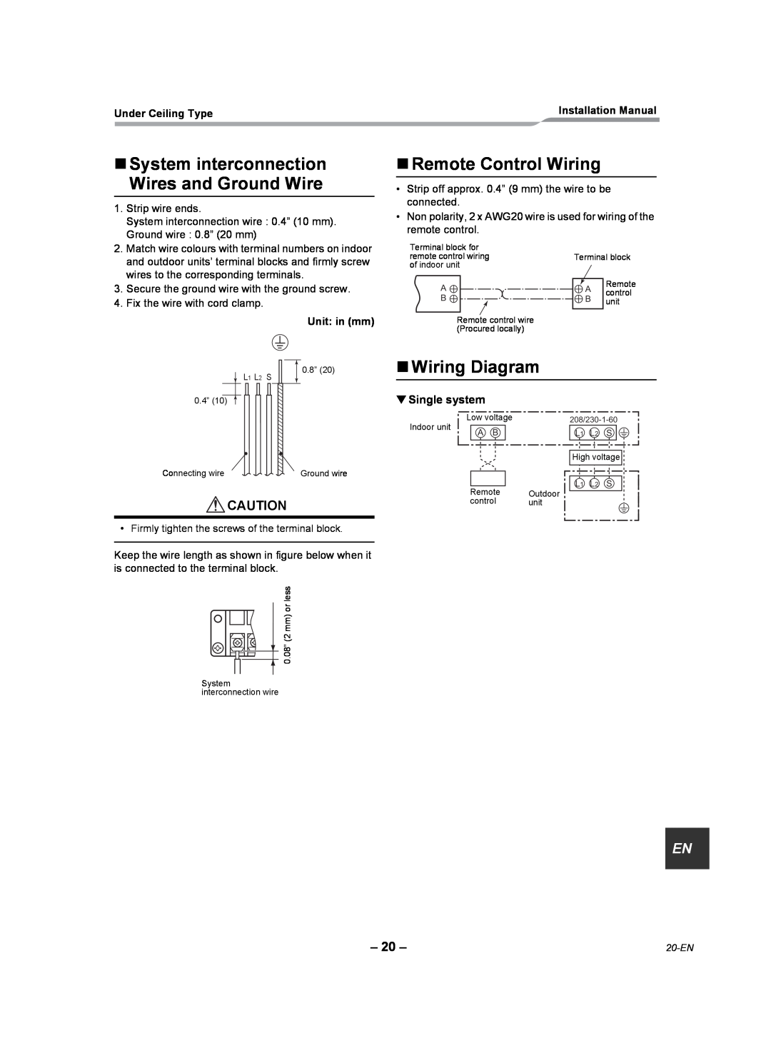
1. Strip wire ends. |
System interconnection wire : 0.4” (10 mm). |
Ground wire : 0.8” (20 mm) |
Remote Control Wiring
•Strip off approx. 0.4” (9 mm) the wire to be connected.
•Non polarity, 2 x AWG20 wire is used for wiring of the remote control.
2. | Match wire colours with terminal numbers on indoor |
| and outdoor units’ terminal blocks and firmly screw |
| wires to the corresponding terminals. |
3. | Secure the ground wire with the ground screw. |
4. | Fix the wire with cord clamp. |
Unit: in (mm)
Terminal block for remote control wiring of indoor unit
A
B
Remote control wire (Procured locally)
Terminal block
A | Remote | |
control | ||
B | ||
unit | ||
|
L1 L2 S
0.8” (20)
Wiring Diagram
0.4” (10)
Connecting wire
Ground wire
▼Single system
Low voltage
Indoor unit
A B
L1 L2 S ![]()
![]()
High voltage
L1 L2 S
![]() CAUTION
CAUTION
• Firmly tighten the screws of the terminal block.
Keep the wire length as shown in figure below when it is connected to the terminal block.

![]() 0.08” (2 mm) or less
0.08” (2 mm) or less
System interconnection wire
Remote Outdoor
control unit
EN |
– 20 – |