Under Ceiling Type | Installation Manual |
Filter sign setting
According to the installation condition, the lighting time of the filter sign (Notification of filter cleaning) can be changed.
Follow to the basic operation procedure
(1 → 2 → 3 → 4 → 5 → 6).
•For the CODE No. in Procedure 3, specify [01].
•For the [SET DATA] in Procedure 4, select the setup data of filter sign lighting time from the following table.
Setup data | Filter sign lighting time |
|
|
0000 | None |
|
|
0001 | 150H |
|
|
0002 | 2500H (Factory default) |
|
|
0003 | 5000H |
|
|
0004 | 10000H |
|
|
To secure better effect of heating
When it is difficult to obtain satisfactory heating due to installation place of the indoor unit or structure of the room, the detection temperature of heating can be raised. Also use a circulator, etc. to circulate heat air near the ceiling.
Follow to the basic operation procedure
(1 → 2 → 3 → 4 → 5 → 6).
•For the CODE No. in Procedure 3, specify [06].
•For the SET DATA in Procedure 4, select the setup data of shift value of detection temperature to be set up from the table below.
Setup data | Detection temp shift value | |
|
| |
0000 | No shift | |
|
| |
0001 | +1.8 °F (+1 °C) | |
|
| |
0002 | +3.6 °F (+2 °C) | |
(Factory default) | ||
| ||
0003 | +5.4 °F (+3 °C) | |
|
| |
0004 | +7.2 °F (+4 °C) | |
|
| |
0005 | +9.0 °F (+5 °C) | |
|
| |
0006 | +10.8 °F (+6 °C) | |
|
|
Group control
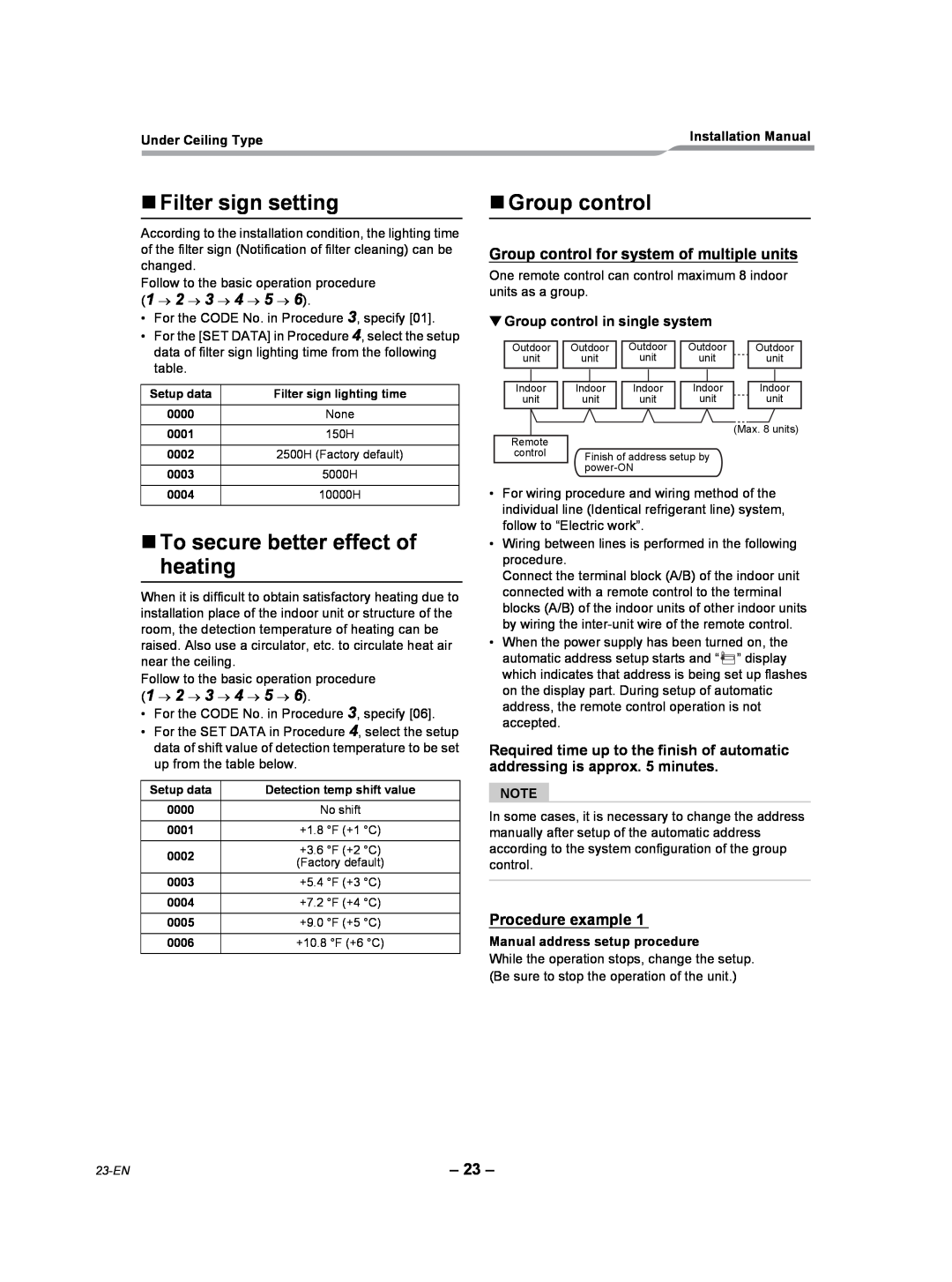
Group control for system of multiple units
One remote control can control maximum 8 indoor units as a group.
▼Group control in single system
Outdoor | Outdoor |
| Outdoor |
| Outdoor |
| Outdoor | ||||
unit | unit |
| unit |
| unit |
| unit | ||||
|
|
|
|
|
|
|
|
|
|
|
|
Indoor | Indoor |
| Indoor |
| Indoor |
| Indoor | ||||
unit | unit |
| unit |
| unit |
| unit | ||||
(Max. 8 units)
Remote
control Finish of address setup by
•For wiring procedure and wiring method of the individual line (Identical refrigerant line) system, follow to “Electric work”.
•Wiring between lines is performed in the following procedure.
Connect the terminal block (A/B) of the indoor unit connected with a remote control to the terminal blocks (A/B) of the indoor units of other indoor units by wiring the
•When the power supply has been turned on, the automatic address setup starts and “![]() ” display which indicates that address is being set up flashes on the display part. During setup of automatic address, the remote control operation is not accepted.
” display which indicates that address is being set up flashes on the display part. During setup of automatic address, the remote control operation is not accepted.
Required time up to the finish of automatic addressing is approx. 5 minutes.
NOTE
In some cases, it is necessary to change the address manually after setup of the automatic address according to the system configuration of the group control.
Procedure example 1
Manual address setup procedure
While the operation stops, change the setup. (Be sure to stop the operation of the unit.)
– 23 – |