Toshiba Corporation
Recording
Playback
Laser Safety
Precautions
Power Supply
On / Standby
Declaration of Conformity
Installation Location
Avoid the Hazards of Electrical Shock and Fire
Moisture Condensation Warning
Accessories Supplied
Purchase a good quality VHS Video Head Cleaner
Maintenance
Video head cleaner before use
Clean video heads only when problems occur
Table of Contents
Recording
Features
Dubbing
Playback
Compatibility
Editing
Disc Mark Specification Remarks
Using different disc types for different purposes
Choosing a Disc
For Recording / Playback
Disc Mark
For Playback Only
10 EN
On DVD-RW Discs
On DVD-R Discs
On DVD+R / DVD+RW Discs
Marks on DVD Video Discs
On Cleaning Discs
Structure of Disc Contents
On Handling Discs
On Storing Discs
Discs and Purposes
14 EN
DVD-V
Symbol Description
16 EN
Functional Overview
Front Panel
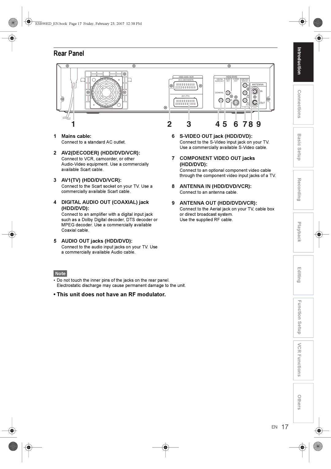
This unit does not have an RF modulator
Rear Panel
Connect to a standard AC outlet
Connect to an antenna cable
18 EN
Remote Control
Displays the Title List
During playback, press to change the audio settings
Press to confirm or select menu items
Press to return to the previously displayed Menu Screen
HDD / DVD / VCR Modes Switching
Installing Batteries in the Remote Control
About the Remote Control
20 EN
How to use Setup Menus
Guide to Setup Menu
Guide to Display Information
Display Example
22 EN
Front Panel Display Guide
Display Messages
Connections
Connecting to a TV
Connections Basic Setup
Digital Audio for Better Sound Quality
Connecting to External Equipment
24 EN
Connections illustrated above are optional for better sound
After You Have Completed Connections
Connecting to an MD deck or DAT deck
For the First Time Use
Press Enter to start Auto Channel Tuning
26 EN
If you like to skip this step, press Return
OSD Language Setting
Select Manual Tuning using Cursor U / D, then press Enter
Manual Tuning
Press Setup in stop mode
28 EN
Select Channel Setting using
When the setup for the position is completed, press Enter
Select Move using Cursor U / D Then press Enter
To Select a Channel
Auto Clock Setting
Setting the Clock
Select Clock Setting using Cursor U / D, then press Enter
30 EN
When all the information is entered, press Enter
Manual Clock Setting
Select On using Cursor U / D, then press Enter
Select TV Aspect using Cursor U / D, then press Enter
Selecting the Sound Mode
Selecting the TV Aspect Ratio
32 EN
Top and bottom of the screen
34 EN
Information on Supported Media
Media Types
Recordable Discs
Rec Mode
Restrictions on Recording
Information on Copy Control
Making Discs Playable in Other DVD Players Finalise
36 EN
HDD is a temporary storage location
About HDD
Formatting a Disc
Select Yes using Cursor L / P, then press Enter
Auto Format
Reformatting a Disc Disc Format
Deleting All Contents in HDD
40 EN
Setting Bilingual Recording Audio
Select Recording using Cursor U / D, then press Enter
Dolby Digital
Recording Audio Select XP
Records Dolby Digital audio for good quality sound
Records Linear PCM audio for the best quality sound
Basic Recording
One-touch Timer Recording OTR
42 EN
Press Stop S to stop the recording
Press Timer Prog
Timer Recording
Preparing for Timer Recording
Timer Programme List will appear
44 EN
Press Timer PROG. to exit
VPS Video Programme System / PDC Programme Delivery Control
Editing the Timer Programming Information
Hints for Timer Recording
Shorter Timer Programming Prog is not recorded
Setting External Input Audio
46 EN
If the recording time entirely overlaps
Preparation of this unit
Satellite Link
Press Satellite Link
48 EN
Information on Dubbing
One Touch Dubbing
There are three ways to start One Touch Dubbing
One Touch Dubbing from HDD or Videotape to DVD
HDD to DVD dubbing
50 EN
Videotape to DVD dubbing
To stop the dubbing in progress
Select Add to Title
Dubbing from HDD / DVD to Videotape
Press Dubbing
To delete a title
52 EN
To move a title
Dubbing will start
Example HDD Original
Bi-directional Dubbing between HDD and DVD
Dubbing Direction will appear
54 EN
When Auto is selected Just Dubbing
To change the title name
To erase all the titles in the Dubbing Title List
Dubbing from Videotape to HDD / DVD
56 EN
Setting for External Connection AV3
Dubbing from the External Devices
Finalise
Select Yes using Cursor L / P
Finalising a Disc
Select Disc Protect using Cursor U / D, then press Enter
Setting Disc Protection
Auto Finalise
58 EN
Disc is protected Default setting is No
Playable Discs
Information on Playback
Colour Systems
Region Codes
Hint for HDD / DVD Playback
Basic Playback
Direct Playback
Playback from the Title List Menu
Playback from the DVD Menu
Changing the Order of the Title Display
Playing Back a Video CD
62 EN
Playing Back a Jpeg
Playing Back an MP3
If a file is selected
If a folder is selected
64 EN
Playing Back a DivX
Stop mode, press TOP Menu to call up the DivX List
To exit the DivX list, press TOP Menu or Return
DivX Subtitle
Select Media Select using Cursor U / D, then press Enter
Select Playback using Cursor U / D, then press Enter
DivX VOD
66 EN
Playing Back Discs Using the Title Menu
Playing Back Discs Using the Disc Menu
Cancelling and Recalling the PBC Function
Playing Back a Video CD Using
PBC Function for Video CDs
Menu
Rapid Playback
Special Playback
Resume Playback
Slow Forward / Slow Reverse Playback
Fast Forward / Fast Reverse Playback
Time Shift Playback
70 EN
Step by Step Playback
Simultaneous Playback Recording
Pause
Variable Replay / Variable Skip
Select Zoom using Cursor U / D, then press Enter
Zoom
72 EN
Repeat Playback
Repeat / Programme Playback / Slide Show
Programme Playback
Press Play P to start programme playback
Search
Using the Search button
Slide Show
74 EN
Switching Audio Soundtrack
Switching Subtitles
Picture Adjustment
Selecting the Format of Audio and Video
Switching Virtual Surround System
Switching Camera Angles
Select Angle using Cursor U / D, then press Enter
76 EN
Available Editing Menus
Guide to the Editing on this Unit
78 EN
Adding or Deleting Chapter Marks Manually
What Are Original and Playlist?
Setup Menu will appear For HDD
Select Playlist using Cursor Then press Enter
Creating Titles to a Playlist
Press Clear
Example HDD PL New
Select Select using Cursor U / D, then press Enter
80 EN
Press Return or Setup twice to exit
Select Title Delete using Cursor U / D, then press Enter
Deleting Titles
Deleting a Title
Select Editing using Cursor U / D, then press Enter
When all the titles are selected, press Clear
Deleting a Scene of a Title
82 EN
Example Playlist
When it reaches the desired start point, press Enter
Press Play P to start play back again
Select Delete using Cursor U / D, then press Enter
When it reaches the desired end point, press Enter
Select Edit Title Name using Cursor U / D, then press Enter
Editing Title Names
Select Protect using Cursor U / D, then press Enter
When you finish entering the title name, press Enter again
Protecting / Undo Protecting Titles
Guide to Edit Title Name
Combining Titles
Press Setup
86 EN
Second will be marked and Confirmation window will appear
Setup Menu will appear
Select Yes using Cursor L / P, then press Enter to exit
Dividing a Title
You only can combine the titles in the same folder
Title is divided
88 EN
Select a desired title you want to divide, then press Enter
Tour of the Setup Menus
Function Setup
Variable Replay
90 EN
Lpcm
Video Out Default Scartrgb
Initial Setting
Select Video Out using Cursor U / D, then press Enter
When you finish with the setting, press Setup to exit
Down Sampling Default 48kHz
Digital Audio Setting
Dolby Digital Default Bit Stream
Mpeg Default PCM
Dynamic Range Control Default On
DTS Default On
Audio Language Default Original
Playback
Disc Menu Language Default English
Subtitle Language Default Off
DivX Subtitle Default Off
When you finish entering the code, press Enter
96 EN
Still Mode Default Auto
Parental Lock Default All
TV System Default PAL
Angle Icon Default Off
Initialise Default No
Select Initialise using Cursor U / D, then press Enter
Fast Dubbing Audio Video Mode Default Off
Noise Reduction Default Off
Select Noise Reduction using Cursor U / D, then press Enter
Recording
Background Colour Default On
Display Device Status Default On
Screen Saver Default On
Display
Accidental erasure prevention
100 EN
Before recording, make sure
Index Search
One-touch Timer Recording
Time Search
EN101
Changing the Video Colour System
Other Operations
Hi-Fi Stereo Sound System
102 EN
EN103
Troubleshooting
Error message for HDD/DVD Possible Cause Solution
104 EN
EN105
Symptom Solution
Playback HDD/DVD
106 EN
EN107
Language Code
Language Code
108 EN
EN109
Glossary
110 EN
Specifications
General
Tuner
EN111