Archer C8 AC1750 Wireless Dual Band Gigabit Router
Click the Disable All button to disable all the entries.
Click the Delete All button to delete all the entries.
Click the Previous button to view the information in the previous screen, click the Next button to view the information in the next screen.
5.14.2System Routing Table
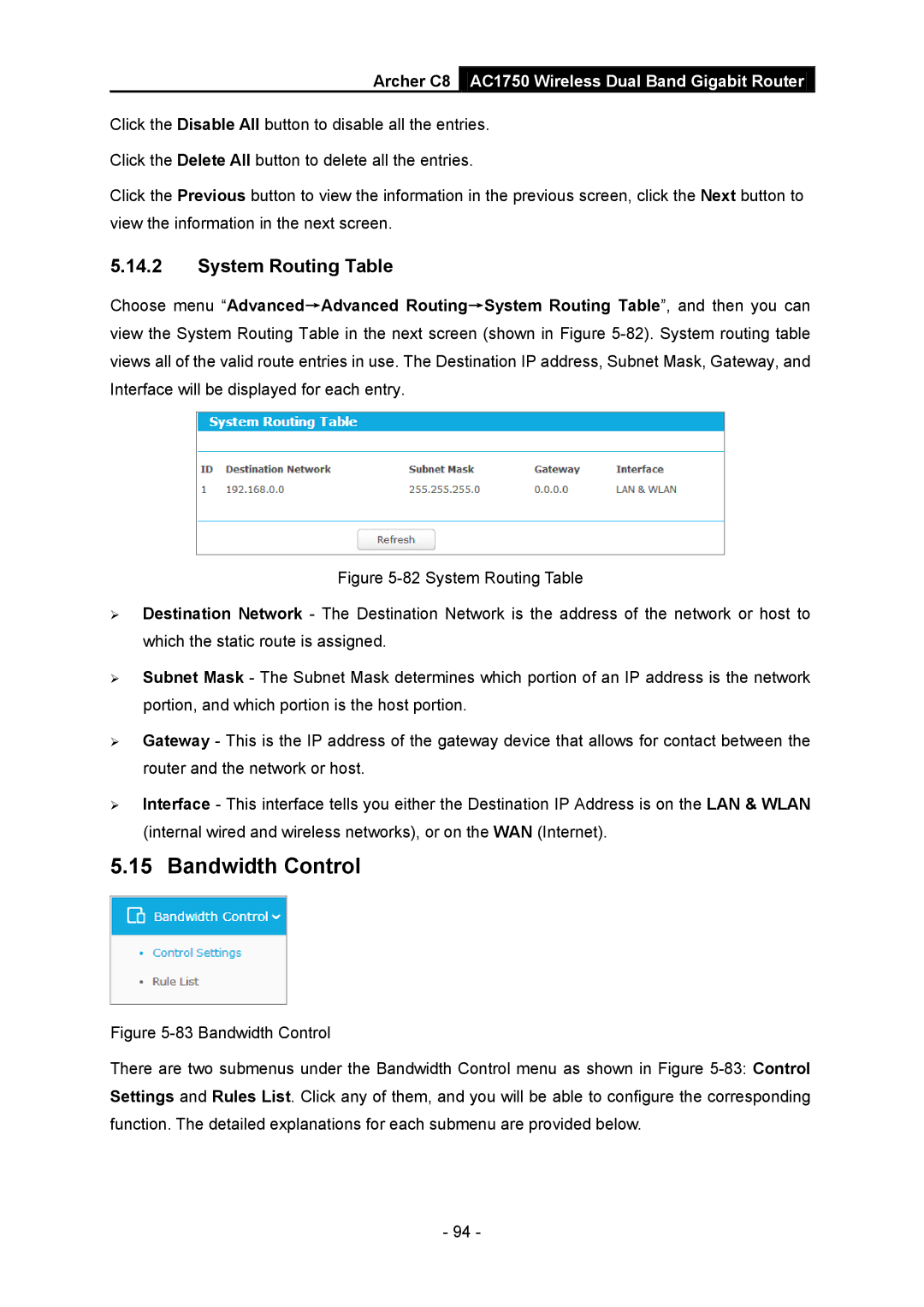
Choose menu “Advanced→Advanced Routing→System Routing Table”, and then you can view the System Routing Table in the next screen (shown in Figure
Figure 5-82 System Routing Table
Destination Network - The Destination Network is the address of the network or host to which the static route is assigned.
Subnet Mask - The Subnet Mask determines which portion of an IP address is the network portion, and which portion is the host portion.
Gateway - This is the IP address of the gateway device that allows for contact between the router and the network or host.
Interface - This interface tells you either the Destination IP Address is on the LAN & WLAN (internal wired and wireless networks), or on the WAN (Internet).
5.15 Bandwidth Control
Figure 5-83 Bandwidth Control
There are two submenus under the Bandwidth Control menu as shown in Figure 5-83: Control Settings and Rules List. Click any of them, and you will be able to configure the corresponding function. The detailed explanations for each submenu are provided below.
- 94 -