Performance
Static Pressure Drops/Fan Drive
Selections
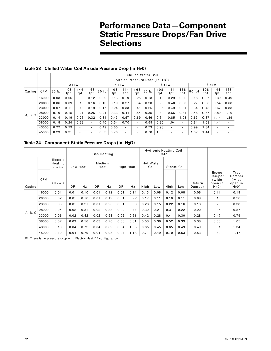
Table 33 Chilled Water Coil Airside Pressure Drop (in H20)
|
|
|
|
|
|
|
| Chilled Water Coil |
|
|
|
|
|
| |||
|
|
|
|
|
|
|
|
|
|
|
|
| |||||
|
|
|
|
|
|
| Airside Pressure Drop (in H2O) |
|
|
|
|
| |||||
|
|
|
|
|
|
|
|
|
|
|
|
|
| ||||
|
|
| 2 row |
|
| 4 row |
|
| 6 row |
|
| 8 row |
| ||||
|
|
|
|
|
|
|
|
|
|
|
|
|
|
|
|
|
|
Casing | CFM | 80 fpf | 108 | 144 | 168 | 80 fpf | 108 | 144 | 168 | 80 fpf | 108 | 144 | 168 | 80 fpf | 108 | 144 | 168 |
fpf | fpf | fpf | fpf | fpf | fpf | fpf | fpf | fpf | fpf | fpf | fpf | ||||||
|
|
|
|
|
|
|
|
|
|
|
|
|
|
|
|
|
|
| 16000 | 0.03 | 0.06 | 0.09 | 0.12 | 0.09 | 0.13 | 0.19 | 0.25 | 0.13 | 0.19 | 0.29 | 0.36 | 0.18 | 0.27 | 0.39 | 0.49 |
|
|
|
|
|
|
|
|
|
|
|
|
|
|
|
|
|
|
| 20000 | 0.06 | 0.09 | 0.13 | 0.16 | 0.13 | 0.19 | 0.27 | 0.34 | 0.20 | 0.28 | 0.40 | 0.50 | 0.27 | 0.38 | 0.54 | 0.68 |
|
|
|
|
|
|
|
|
|
|
|
|
|
|
|
|
|
|
| 23000 | 0.07 | 0.11 | 0.16 | 0.19 | 0.17 | 0.24 | 0.33 | 0.41 | 0.25 | 0.35 | 0.49 | 0.61 | 0.34 | 0.48 | 0.67 | 0.83 |
|
|
|
|
|
|
|
|
|
|
|
|
|
|
|
|
|
|
A, B, C | 28000 | 0.10 | 0.15 | 0.21 | 0.26 | 0.24 | 0.33 | 0.44 | 0.54 | 0.35 | 0.49 | 0.66 | 0.81 | 0.48 | 0.67 | 0.89 | 1.10 |
| 33000 | 0.14 | 0.19 | 0.26 | 0.32 | 0.31 | 0.43 | 0.57 | 0.69 | 0.46 | 0.64 | 0.85 | 1.03 | 0.63 | 0.87 | 1.14 | 1.39 |
|
|
|
|
|
|
|
|
|
|
|
|
|
|
|
|
|
|
| 38000 | 0.18 | 0.24 | 0.33 | - | 0.40 | 0.54 | 0.70 | - | 0.59 | 0.80 | 1.04 | - | 0.81 | 1.09 | 1.41 | - |
|
|
|
|
|
|
|
|
|
|
|
|
|
|
|
|
|
|
| 43000 | 0.22 | 0.29 | - | - | 0.49 | 0.65 | - | - | 0.73 | 0.98 | - | - | 0.99 | 1.34 | - | - |
|
|
|
|
|
|
|
|
|
|
|
|
|
|
|
|
|
|
| 45000 | 0.23 | 0.31 | - | - | 0.53 | 0.70 | - | - | 0.78 | 1.05 | - | - | 1.07 | 1.44 | - | - |
|
|
|
|
|
|
|
|
|
|
|
|
|
|
|
|
|
|
Table 34 Component Static Pressure Drops (in. H2O)
|
|
|
|
|
|
|
|
| Hydronic Heating Coil |
|
|
| ||||
|
|
|
|
| Gas Heating |
|
|
| Data |
|
|
|
| |||
|
|
|
|
|
|
|
|
|
|
|
|
|
|
|
| |
|
| Electric |
|
| Medium |
|
| Hot Water |
|
|
|
|
| |||
|
| Heating |
|
|
|
|
|
|
|
|
| |||||
|
| (Horiz.) | Low Heat | Heat | High Heat | Coil | Steam Coil |
|
|
| ||||||
|
|
|
|
|
|
|
|
|
|
|
|
|
| Econo | Traq | |
|
|
|
|
|
|
|
|
|
|
|
|
|
| |||
| CFM |
|
|
|
|
|
|
|
|
|
|
|
| Damper | Damper | |
| All kw's |
|
|
|
|
|
|
|
|
|
| Return | (wide | (wide | ||
|
|
|
|
|
|
|
|
|
|
|
| open in | open in | |||
Casing |
| (i) | DF | Hz | DF | Hz | DF | Hz | High | Low | High | Low | Damper | H20) | H20) | |
|
|
|
|
|
|
|
|
|
|
|
|
|
|
|
| |
| 16000 | 0.01 | 0.01 | 0.10 | 0.01 | 0.12 | 0.01 | 0.14 | 0.13 | 0.08 | 0.12 | 0.08 | 0.06 | 0.11 | 0.19 | |
|
|
|
|
|
|
|
|
|
|
|
|
|
|
|
| |
| 20000 | 0.02 | 0.01 | 0.16 | 0.01 | 0.19 | 0.01 | 0.22 | 0.17 | 0.11 | 0.16 | 0.11 | 0.09 | 0.15 | 0.26 | |
|
|
|
|
|
|
|
|
|
|
|
|
|
|
|
| |
| 23000 | 0.03 | 0.01 | 0.21 | 0.01 | 0.26 | 0.01 | 0.30 | 0.23 | 0.15 | 0.22 | 0.16 | 0.13 | 0.23 | 0.38 | |
|
|
|
|
|
|
|
|
|
|
|
|
|
|
|
| |
A, B, C | 28000 | 0.04 | 0.02 | 0.31 | 0.02 | 0.38 | 0.02 | 0.44 | 0.32 | 0.21 | 0.31 | 0.22 | 0.20 | 0.34 | 0.57 | |
33000 | 0.06 | 0.02 | 0.42 | 0.02 | 0.53 | 0.02 | 0.61 | 0.42 | 0.28 | 0.41 | 0.30 | 0.28 | 0.47 | 0.79 | ||
| ||||||||||||||||
|
|
|
|
|
|
|
|
|
|
|
|
|
|
|
| |
| 38000 | 0.07 | 0.03 | 0.56 | 0.03 | 0.70 | 0.03 | 0.81 | 0.53 | 0.36 | 0.52 | 0.39 | 0.38 | 0.63 | 1.05 | |
|
|
|
|
|
|
|
|
|
|
|
|
|
|
|
| |
| 43000 | 0.10 | 0.04 | 0.72 | 0.04 | 0.89 | 0.04 | 1.03 | 0.65 | 0.45 | 0.65 | 0.49 | 0.49 | 0.81 | 1.34 | |
|
|
|
|
|
|
|
|
|
|
|
|
|
|
|
| |
| 45000 | 0.10 | 0.04 | 0.79 | 0.04 | 0.98 | 0.04 | 1.13 | 0.71 | 0.49 | 0.70 | 0.53 | 0.53 | 0.89 | 1.47 | |
|
|
|
|
|
|
|
|
|
|
|
|
|
|
|
| |
(i)There is no pressure drop with Electric Heat DF configuration
72 |