Applications Considerations
will help reduce sound transmission. The ASHRAE publication "A Practical Guide to Noise and Vibration Control for HVAC Systems" also provides valuable information.
There are several other sources of unit sound, i.e., supply fan, exhaust/ return fans, and aerodynamic noise generated at the duct fittings. Refer to the ASHRAE Applications Handbook, Chapter 47, 2003 edition for guidelines for minimizing the generation of aerodynamic noise associated with duct fittings. A good source of information on general acoustical considerations for air handlers is the 2000 ASHRAE Journal article titled, "Controlling Noise from Large Rooftop Units".
The Trane Acoustic Program (TAP) allows complete modeling of air handler acoustical installation parameters. The software models airborne sound from supply and return ducts, as well as duct breakout and roof transmission sound, so that the designer can identify potential sound problems and make design alterations before equipment installation. Output of the program shows the resulting NC (or RC) level for any point in the occupied space. TAP is also capable of modeling the effect of outdoor sound on the surrounding area. This program is available from Trane's Customer Direct Service NetworkTM (C.D.S.), ask your local Trane representative for additional information on this program.
Clearance Requirements
The recommended clearances identified in Figure 31, p. 85 should be maintained to assure adequate service capability, maximum capacity and peak operating efficiency. If the clearances shown are not possible on a particular job, consider the following:
•Do the clearances available allow for major service work such as changing coils?
•Do the clearances available allow for proper outside air intake and exhaust air removal?
•If screening around the unit is being used, is there a possibility of air recirculation from the exhaust to the outside air intake?
26
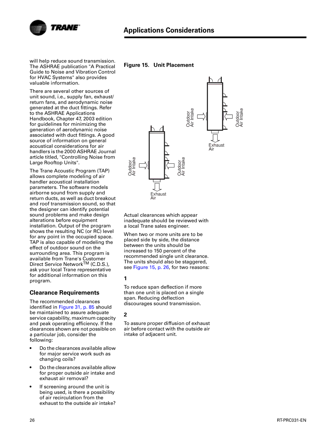
Figure 15. Unit Placement
Air Intake
Outdoor
Exhaust
Air
Outdoor Air Intake | Outdoor Air Intake |
Exhaust
Air
Actual clearances which appear inadequate should be reviewed with a local Trane sales engineer.
When two or more units are to be placed side by side, the distance between the units should be increased to 150 percent of the recommended single unit clearance. The units should also be staggered, see Figure 15, p. 26, for two reasons:
1
To reduce span deflection if more than one unit is placed on a single span. Reducing deflection discourages sound transmission.
2
To assure proper diffusion of exhaust air before contact with the outside air intake of adjacent unit.
Outdoor Air Intake
