Dimensional Data
Minimum Clearance Details
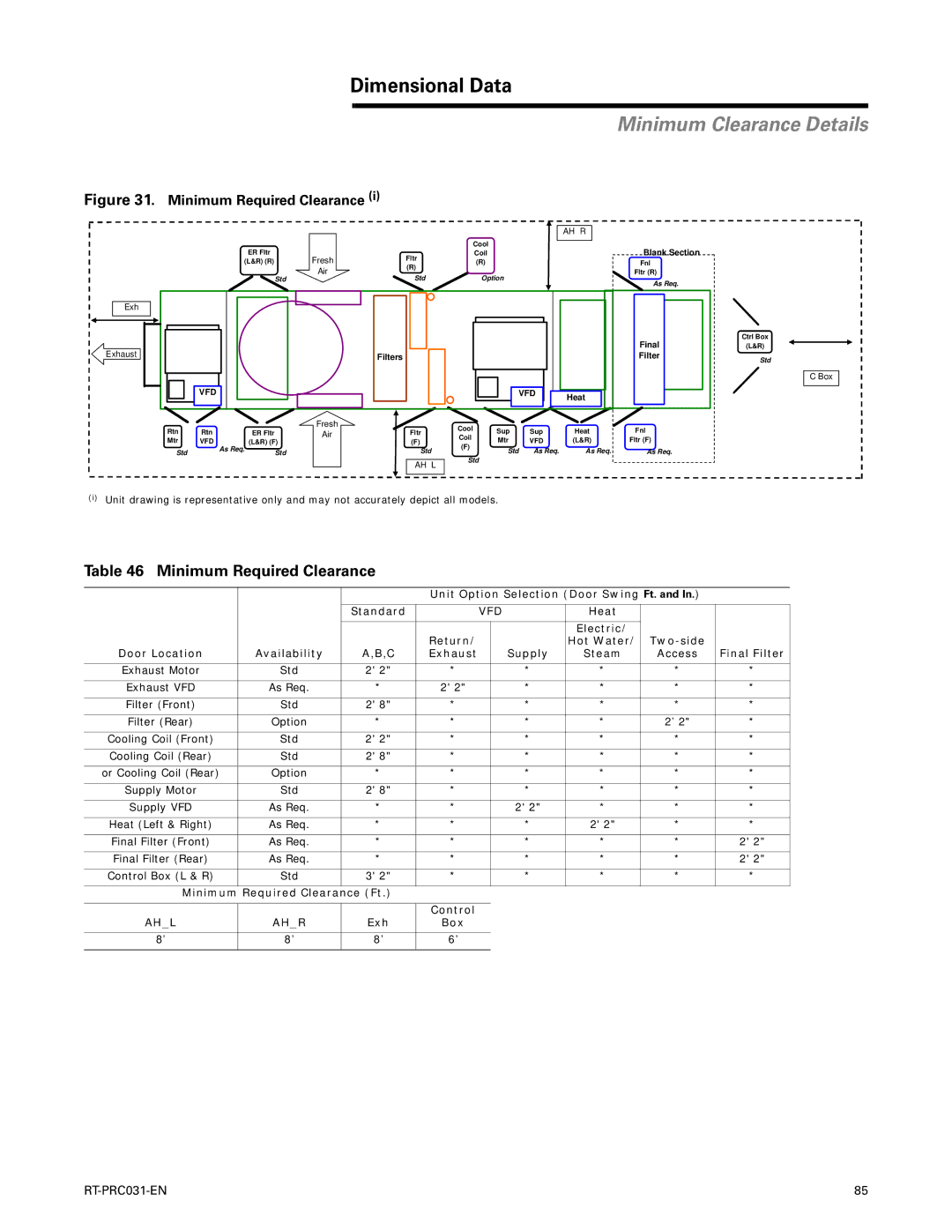
Figure 31. Minimum Required Clearance (i)
|
|
|
|
|
|
|
| AH R | |
|
| ER Fltr |
|
|
| Cool |
|
| |
|
| Fresh | Fltr |
| Coil |
|
| ||
| (L&R) (R) |
| (R) |
|
| ||||
|
|
| Air | (R) |
|
|
|
| |
|
| Std | Std |
| Option |
|
| ||
|
|
|
|
|
| ||||
Exh |
|
|
|
|
|
|
|
| |
Exhaust |
|
|
| Filters |
|
|
|
| |
|
|
|
|
|
|
|
| ||
| VFD |
|
|
|
| VFD | Heat | ||
|
|
|
|
|
|
|
| ||
Rtn | Rtn | ER Fltr | Fresh | Fltr | Cool | Sup | Sup | Heat | |
Air | |||||||||
Coil | |||||||||
Mtr | VFD | (L&R) (F) |
| (F) | Mtr | VFD | (L&R) | ||
| (F) | ||||||||
Std | As Req. | Std |
| Std | Std | As Req. | As Req. | ||
|
| ||||||||
|
|
|
| AH L | Std |
|
| ||
|
|
|
|
|
|
|
| ||
Blank Section
Fnl
Fltr (R)
As Req.
Final
Filter
Fnl
Fltr (F)
As Req.
Ctrl Box
(L&R)
Std
C Box
(i)Unit drawing is representative only and may not accurately depict all models.
Table 46 Minimum Required Clearance
|
|
| Unit Option Selection (Door Swing Ft. and In.) |
| ||||
|
|
|
|
|
|
|
|
|
|
| Standard |
| VFD | Heat |
|
| |
|
|
|
|
|
|
|
|
|
|
|
| Return/ |
|
| Electric/ |
|
|
|
|
|
|
| Hot Water/ |
| ||
Door Location | Availability | A,B,C | Exhaust |
| Supply | Steam | Access | Final Filter |
|
|
|
|
|
|
|
|
|
Exhaust Motor | Std | 2' 2" | * |
| * | * | * | * |
|
|
|
|
|
|
|
|
|
Exhaust VFD | As Req. | * | 2' 2" |
| * | * | * | * |
|
|
|
|
|
|
|
|
|
Filter (Front) | Std | 2' 8" | * |
| * | * | * | * |
|
|
|
|
|
|
|
|
|
Filter (Rear) | Option | * | * |
| * | * | 2’ 2" | * |
|
|
|
|
|
|
|
|
|
Cooling Coil (Front) | Std | 2' 2" | * |
| * | * | * | * |
|
|
|
|
|
|
|
|
|
Cooling Coil (Rear) | Std | 2' 8" | * |
| * | * | * | * |
|
|
|
|
|
|
|
|
|
or Cooling Coil (Rear) | Option | * | * |
| * | * | * | * |
|
|
|
|
|
|
|
|
|
Supply Motor | Std | 2' 8" | * |
| * | * | * | * |
|
|
|
|
|
|
|
|
|
Supply VFD | As Req. | * | * |
| 2' 2" | * | * | * |
|
|
|
|
|
|
|
|
|
Heat (Left & Right) | As Req. | * | * |
| * | 2' 2" | * | * |
|
|
|
|
|
|
|
|
|
Final Filter (Front) | As Req. | * | * |
| * | * | * | 2' 2" |
|
|
|
|
|
|
|
|
|
Final Filter (Rear) | As Req. | * | * |
| * | * | * | 2' 2" |
|
|
|
|
|
|
|
|
|
Control Box (L & R) | Std | 3' 2" | * |
| * | * | * | * |
|
|
|
|
|
|
|
|
|
Minimum | Required Clearance (Ft.) |
|
|
|
|
|
| |
|
|
|
|
|
|
|
|
|
|
|
| Control |
|
|
|
|
|
AH_L | AH_R | Exh | Box |
|
|
|
|
|
|
|
|
|
|
|
|
|
|
8’ | 8’ | 8’ | 6’ |
|
|
|
|
|
|
|
|
|
|
|
|
|
|
85 |