Disconnect Switch External Handle
(Factory Mounted Option)
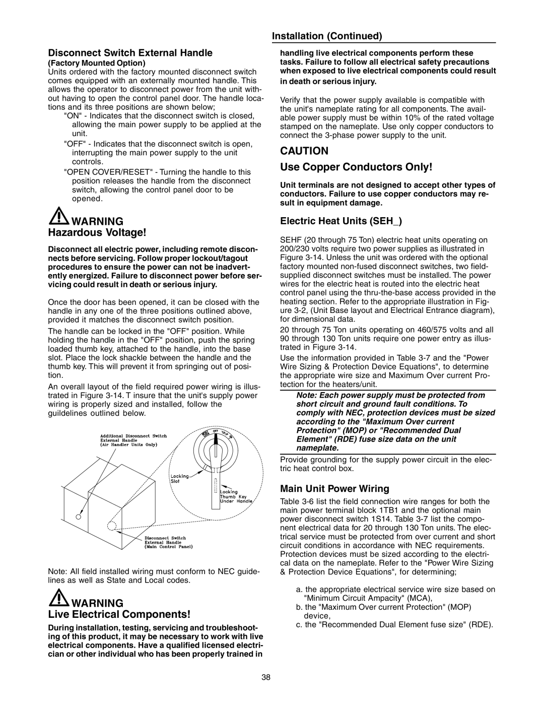
Units ordered with the factory mounted disconnect switch comes equipped with an externally mounted handle. This allows the operator to disconnect power from the unit with- out having to open the control panel door. The handle loca- tions and its three positions are shown below;
"ON" - Indicates that the disconnect switch is closed, allowing the main power supply to be applied at the unit.
"OFF" - Indicates that the disconnect switch is open, interrupting the main power supply to the unit controls.
"OPEN COVER/RESET" - Turning the handle to this position releases the handle from the disconnect switch, allowing the control panel door to be opened.
![]() WARNING
WARNING
Hazardous Voltage!
Disconnect all electric power, including remote discon- nects before servicing. Follow proper lockout/tagout procedures to ensure the power can not be inadvert- ently energized. Failure to disconnect power before ser- vicing could result in death or serious injury.
Once the door has been opened, it can be closed with the handle in any one of the three positions outlined above, provided it matches the disconnect switch position.
The handle can be locked in the "OFF" position. While holding the handle in the "OFF" position, push the spring loaded thumb key, attached to the handle, into the base slot. Place the lock shackle between the handle and the thumb key. This will prevent it from springing out of posi- tion.
An overall layout of the field required power wiring is illus- trated in Figure
Note: All field installed wiring must conform to NEC guide- lines as well as State and Local codes.
![]() WARNING
WARNING
Live Electrical Components!
During installation, testing, servicing and troubleshoot- ing of this product, it may be necessary to work with live electrical components. Have a qualified licensed electri- cian or other individual who has been properly trained in
Installation (Continued)
handling live electrical components perform these tasks. Failure to follow all electrical safety precautions when exposed to live electrical components could result
in death or serious injury.
Verify that the power supply available is compatible with the unit's nameplate rating for all components. The avail- able power supply must be within 10% of the rated voltage stamped on the nameplate. Use only copper conductors to connect the
CAUTION
Use Copper Conductors Only!
Unit terminals are not designed to accept other types of conductors. Failure to use copper conductors may re- sult in equipment damage.
Electric Heat Units (SEH_)
SEHF (20 through 75 Ton) electric heat units operating on 200/230 volts require two power supplies as illustrated in Figure
20 through 75 Ton units operating on 460/575 volts and all 90 through 130 Ton units require one power entry as illus- trated in Figure
Use the information provided in Table
Note: Each power supply must be protected from short circuit and ground fault conditions. To comply with NEC, protection devices must be sized according to the "Maximum Over current Protection" (MOP) or "Recommended Dual Element" (RDE) fuse size data on the unit nameplate.
Provide grounding for the supply power circuit in the elec- tric heat control box.
Main Unit Power Wiring
Table
&Protection Device Equations", for determining;
a.the appropriate electrical service wire size based on "Minimum Circuit Ampacity" (MCA),
b.the "Maximum Over current Protection" (MOP) device,
c.the "Recommended Dual Element fuse size" (RDE).
38