Models
Later Design Sequence
With 3-DTMScroll Compressors
Overview of Manual
Literature Change History
Table of Contents
Model Number Description
General Information
Digit 3 Unit Airflow
Unit Description
Fiberglass Wool
Hazard Identification
General Information Commonly Used Acronyms
Supply AIR
General Information
CFM
Ventilation Control Module VCM Design special option only
Lead-Lag
Constant Volume CV Units
Unit Component Layout and Shipwith Locations
Variable Air Volume VAV Units
General Information Space Temperature Averaging
Control Module Locations for SHF 40, 60, 70 & 75 Ton Units
Table of Contents
Storage
Unit Dimensions & Weight Information
No Step Surface
Unit Inspection As soon as the unit arrives at the job site
Page
Sahf Cooling-Only Units 20 thru 75 Ton
Electrical Entrance Data Unit Dimensions
Installation
Unit Dimensional Data Dimensions Size
Unit Base Dimensional Data Dimensions
SEHF, SFHF, SLHF, SSHF, Sxhf Units 20 thru 75 Ton
Unit Size Furnace Dimensions Note Size/MBH Length Height
Unit Base Dimensional Data Dimensions Size
Unit Dimensions Size
Electrical Entrance Data Unit Dimensions Size
SHG Cooling & Heating Units 90 through 130 Ton
Sshf
Sahf
Sehf
Slhf
Roof Curb and Ductwork
SE,SL
Sahf Sshf Sfhf Sxhf Sehg Sfhg Sxhg HF/G
Pitch Pocket Location
Installation Unit Rigging & Placement
If a Trane Curb Accessory Kit is not used
Heavy Objects
Typical Unit Rigging Unit Base & Roof Curb Section
Requirements for Electric Heat Units
Main Electrical Power Requirements
Installation Field Installed Control Wiring
General Unit Requirements
Installation
Condensate Drain Connections
Page
Removing Supply and Exhaust Fan Shipping Channels Motors 5Hp
Page
Units with StatitracTM
Installation Sensor & Tubing Installation
Connecting the Gas Supply Line to the Furnace Gas Train
Hazardous Gases and Flammable Vapors
Gas Heat Units SFH
350 MBH 850 MBH
Hot Water Heat Units SLH
Flue Assembly Installation
Flue Assembly
1000 MBH Modulating 500 MBH 1000 MBH
SSHG-90
Steam Heat Units SSH
Through 130 Ton units
Page
Hazardous Voltage
Live Electrical Components
Use Copper Conductors Only
Typical Field Power Wiring 20 thru 75 Ton
Page
FLA
Supply Fan Motor FLA ea Horsepower
Condenser Fans Total FLA
Exhaust Fan Motor
Combustion
Blower Motor Sfhf Only
Unit Tonnage No. of Compressors Tonnage Type Designation
On the Next
Single Source Power 380V, 415V, 460V,
Load Definitions Load
= Current of the Largest Motor Compressor or FAN Motor
MCA = 1.25 x Load MOP = 1.25 x Load
Power Wire Sizing and Protection Device Equations
Disconnect Switch Sizing DSS
Dual Source Power units 200V
Controls using 24 VAC
Installation Controls using DC Analog Input/Outputs
Constant Volume System Controls
Constant Volume or Variable Air Volume System Controls
Variable Air Volume System Controls
Depressurize
Pressurize
Fire
Purge
16A
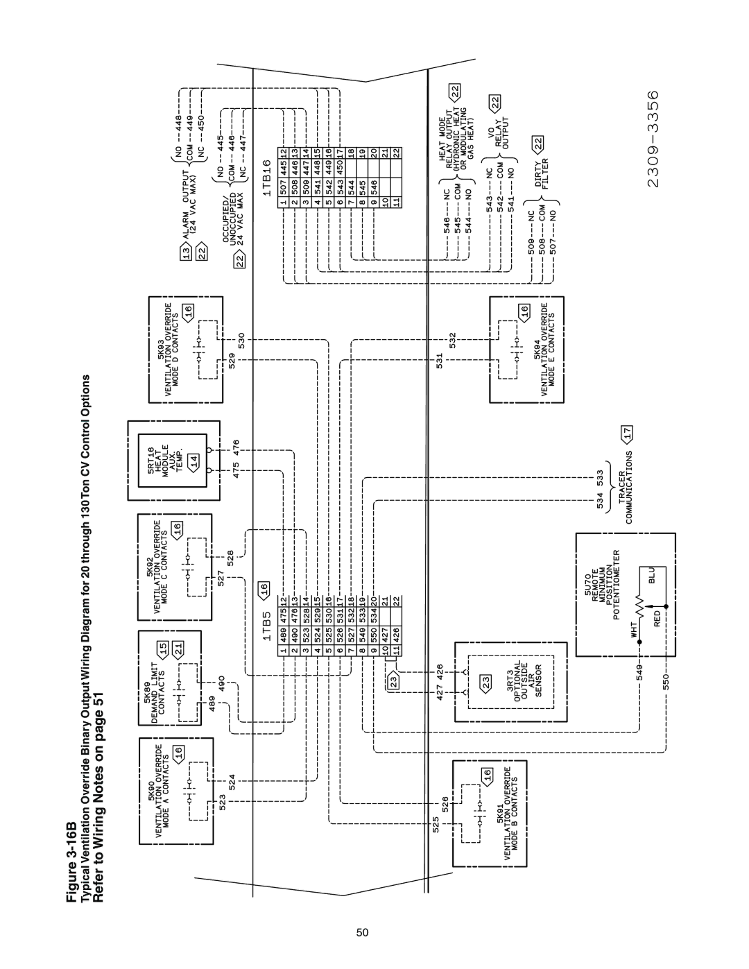
Refer to Wiring Notes on
16B
Page
17A
17B
Input Voltage
VAV Setpoint
Table of Contents
Sequence of Operation
Cooling Sequence of Operation
Propane Gas
Gas Heating Sequence of Operation
Fenwal Ignition System
Unit Start-Up
Modulating Gas Sequence of Operation
Flame Failure
Full and Limited Modulating Gas Furnace
Electric Heat Sequence of Operation
Unit Start-Up Wet Heat Sequence of Operation
Freeze Protection
Unit Power
Compressor Damage
Electrical Phasing
Voltage Supply and Voltage Imbalance
Voltage Supply
Voltage Imbalance
IGV
Service Test Guide for Component Operation
Supply FAN
If all of the fans are rotating backwards
System Airflow Measurements Constant Volume Systems
Rotating Components
Verifying Proper Fan Rotation
Condenser Fan Location with Human Interface Designator
Variable Air Volume Systems
Optional with all units equipped with an economizer
Exhaust Airflow Measurement
TraqTM Sensor Airflow Measurement
Optional with all Units
Ton Supply Fan Performance without Inlet Guide Vanes
20 & 25 Ton Supply Fan Performance without Inlet Guide Vanes
Wocfm 1200 RPM 40 HP 40%
300 RP
Standard Evaporator Coil
20000 30000 40000 50000 60000
Drop
Ton Supply Fan Performance with Inlet Guide Vanes
20 & 25 Ton Supply Fan Performance with Inlet Guide Vanes
15 HP 900 RPM 80% 10 HP
RPM
AIR
Through 75 Ton Component Static Pressure Drops Inches W.C
STD
AIR
CFM RPM BHP
HF-C30 000
HF-C20 000
HF-C25 000
10,000
AIR RPM BHP
RPM BHP BHP RPM BHP RPM BHP
Fresh Air & Return Air Damper Operation
Economizer Damper Adjustment
To Adjust the Fresh Air Damper Travel
Exhaust Air Dampers
Ton Units
Damper Travel Adjustment Position
Connecting Rod Crank Arm Hole
Configuration
70 & 105 Ton
Fresh Air & Return Air Linkage Adjustment
Compressor Start-Up
All Systems
At Low Ambient Start-Up
Compressor Operational Sounds
Refrigerant Charging
At Shutdown
Compressor Locations
Cooling Cycle Pressure Curve
340 320
Full Load
380 360 340 OD Ambient
Full Load
380 360 340 OD Ambient 320
240 220
380 360 OD Ambient
Thermostatic Expansion Valves
Charging by Subcooling
Low Ambient Dampers
Gas Furnace Start-Up
Electric, Steam and Hot Water Start-Up
Two Stage Gas Furnace
High-Fire Adjustment
Combustion Air Adjustment O2
Low-Fire Adjustment 500 MBH, 850 & 1,000 MBH only
MBH
Firing Manifold
CO2 Pressure
Full Modulating Gas Furnace
Heat Exchanger
Unit control
Limited Modulating Gas Furnace Unit Start-Up
Modulating Gas Regulator
Modulating Gas Regulator Legend
Typical Gas Furnace
Unit Start-Up Final Unit Checkout
Service & Maintenance
Unit Internal Fuse Replacement Data & VFD Factory Settings
Service & Maintenance
Model Type
Unit Model Box-type Note Qty
Qty Size of each
Wet Heat Coil Fin Data Total Coil Fins
Service & Maintenance
Fan Belt Adjustment
Scroll Compressor Replacement
Suction Line Filter/Drier Installation
Gripbelts Gripnotch Cross Small P.D Section Range Min Max
Hazardous Voltage! w/Capacitors
VFD Programming Parameters
Supply and Exhaust Fan VFD Programming Parameters
Service & Maintenance Monthly Maintenance
Filters
Cooling Season
Heating Season
Coil Cleaning
Coil Cleaners
Contains Refrigerant
Steam or Hot Water Coils
Final Process
Index
See Figure Gate type valve 36-37 See -12 Figure
See VOM Contacts -16 Figure
Equipment Damage From Ultraviolet UV Lights
Warranty and Liability Clause
115
116