TS32M~1GCF80 |
|
| 80X CompactFlash Card | |||
|
|
|
|
|
|
|
|
|
|
|
| ||
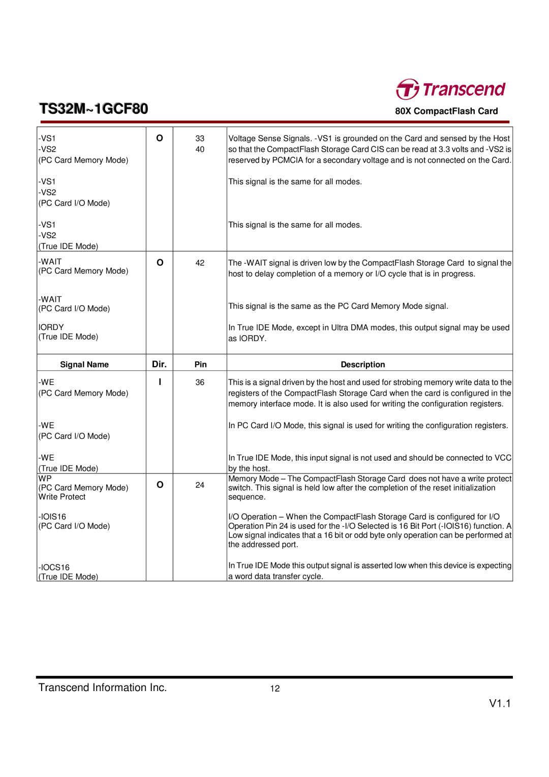
| O | 33 | Voltage Sense Signals. | |||
|
| 40 | so that the CompactFlash Storage Card CIS can be read at 3.3 volts and | |||
(PC Card Memory Mode) |
|
|
| reserved by PCMCIA for a secondary voltage and is not connected on the Card. | ||
|
|
| This signal is the same for all modes. | |||
|
|
|
|
| ||
(PC Card I/O Mode) |
|
|
|
|
| |
|
|
| This signal is the same for all modes. | |||
|
|
|
|
| ||
(True IDE Mode) |
|
|
|
|
| |
| O | 42 | The | |||
(PC Card Memory Mode) |
|
|
| host to delay completion of a memory or I/O cycle that is in progress. | ||
|
|
|
|
| ||
|
|
| This signal is the same as the PC Card Memory Mode signal. | |||
(PC Card I/O Mode) |
|
|
| |||
|
|
|
|
| ||
IORDY |
|
|
| In True IDE Mode, except in Ultra DMA modes, this output signal may be used | ||
(True IDE Mode) |
|
|
| as IORDY. | ||
|
|
|
|
|
| |
| Signal Name |
| Dir. | Pin | Description | |
|
|
|
|
| ||
| I | 36 | This is a signal driven by the host and used for strobing memory write data to the | |||
(PC Card Memory Mode) |
|
|
| registers of the CompactFlash Storage Card when the card is configured in the | ||
|
|
|
|
| memory interface mode. It is also used for writing the configuration registers. | |
|
|
| In PC Card I/O Mode, this signal is used for writing the configuration registers. | |||
(PC Card I/O Mode) |
|
|
|
|
| |
|
|
| In True IDE Mode, this input signal is not used and should be connected to VCC | |||
(True IDE Mode) |
|
|
| by the host. | ||
WP |
| O | 24 | Memory Mode – The CompactFlash Storage Card does not have a write protect | ||
(PC Card Memory Mode) |
| switch. This signal is held low after the completion of the reset initialization | ||||
|
|
| ||||
Write Protect |
|
|
| sequence. | ||
|
|
| I/O Operation – When the CompactFlash Storage Card is configured for I/O | |||
(PC Card I/O Mode) |
|
|
| Operation Pin 24 is used for the | ||
|
|
|
|
| Low signal indicates that a 16 bit or odd byte only operation can be performed at | |
|
|
|
|
| the addressed port. | |
|
|
| In True IDE Mode this output signal is asserted low when this device is expecting | |||
|
|
|
|
| ||
(True IDE Mode) |
|
|
| a word data transfer cycle. | ||
Transcend Information Inc. | 12 |