TS32M~1GCF80 | 80X CompactFlash Card | |
|
|
|
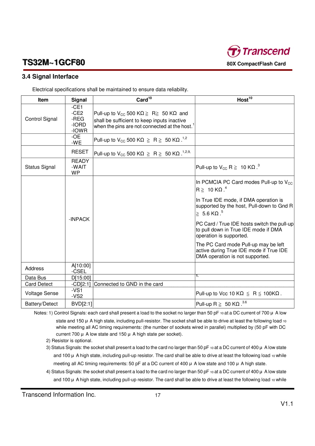
3.4 Signal Interface
Electrical specifications shall be maintained to ensure data reliability.
Item | Signal | Card10 |
|
|
|
|
|
|
|
|
| Host10 | |||
|
|
|
|
|
|
|
|
|
|
|
|
|
|
| |
|
| R | 50 K | and |
|
|
|
|
|
|
|
| |||
Control Signal | shall be sufficient to keep inputs inactive |
|
|
|
|
|
|
|
| ||||||
| 1 |
|
|
|
|
|
|
| |||||||
| when the pins are not connected at the host. |
|
|
|
|
|
|
| |||||||
|
|
|
|
|
|
|
|
| |||||||
|
|
|
|
|
|
|
|
|
|
|
|
|
|
| |
|
| R | 50 K | .1,2 |
|
|
|
|
|
|
|
| |||
|
|
|
|
|
|
|
|
|
|
|
|
|
|
| |
| RESET | 1,2,9, |
|
|
|
|
|
|
|
| |||||
|
|
|
|
|
|
|
|
|
|
| |||||
|
|
|
|
|
|
|
|
|
|
|
|
|
|
|
|
| READY |
| Ω ≧ | ≧ | Ω |
|
|
|
|
|
|
|
|
| .3 |
Status Signal |
|
|
|
|
| 10 K | |||||||||
| WP |
|
|
|
|
|
|
|
|
|
|
| |||
|
|
|
|
|
|
|
|
| In PCMCIA PC Card modes | ||||||
|
|
|
|
|
|
|
|
| R |
| 10 K | .4 |
|
|
|
|
|
|
|
|
|
|
|
| In True IDE mode, if DMA operation is | ||||||
|
|
|
|
|
|
|
|
| supported by the host, | ||||||
|
|
|
|
|
|
|
|
|
| 5.6 K | .5 |
|
|
| |
|
|
|
|
|
|
|
| PC Card / True IDE hosts switch the | |||||||
|
|
|
|
|
|
|
|
| |||||||
|
|
|
|
|
|
|
|
| to pull down in True≧ | IDE | Ωmode if DMA | ||||
|
|
|
|
|
|
|
|
| operation is supported. |
| |||||
|
|
|
|
|
|
|
|
| The PC Card mode | ||||||
|
|
|
|
|
|
|
|
| active during True IDE mode if True IDE | ||||||
|
|
|
|
|
|
|
|
|
| ≧ |
| Ω |
|
|
|
|
|
|
|
|
|
|
|
| DMA operation is not supported. | ||||||
|
|
|
|
|
|
|
|
|
|
|
|
|
|
|
|
Address | A[10:00] |
|
|
|
|
|
|
|
|
|
|
|
|
|
|
|
|
|
|
|
|
|
|
|
|
|
|
|
|
| |
|
|
|
|
|
|
|
|
|
|
|
|
|
|
| |
Data Bus | D[15:00] |
|
|
|
|
|
|
| 1. |
| Ω |
|
|
| |
|
|
|
|
|
|
| ≧ |
|
|
|
| ||||
Card Detect | Connected to GND in the card |
|
|
|
|
|
|
|
|
|
| ||||
Voltage Sense |
|
|
|
|
|
|
|
| R 100K . | ||||||
|
|
|
|
|
|
|
| ||||||||
|
|
|
|
|
|
|
|
|
|
|
|
|
|
| |
Battery/Detect | BVD[2:1] |
|
|
|
|
|
|
| 50 K |
| .3.6 |
| |||
Notes: 1) Control Signals: each card shall present a load to the socket no larger than 50 pF 10 at a DC current of 700 A low
state and 150 A high state, including
current 700 A low state and 150 |
| A high state per socket). |
|
|
|
|
|
|
|
| ||
2) Resistor is optional. |
|
|
|
|
|
|
|
|
|
| ||
3) Status Signals: the socket shall present a load to the card no larger than 50 pF 10 at a DC current of 400 |
| A low state | ||||||||||
and 100 | A high state, including | |||||||||||
|
|
|
|
|
| Ω | Ω ≦ | ≦ |
|
| Ω | |
meeting all AC timing requirements: 50 pF at a DC current of 400 A low state and 100 | A high state. |
|
| |||||||||
|
|
|
|
| ≧ |
|
|
| A low state | |||
4) Status Signals: the socket shall present a load to the card no larger than 50 pF 10 at a DC current of 400 |
| |||||||||||
|
|
|
|
|
|
|
|
|
|
| μ |
|
and 100 A high state, including | ||||||||||||
|
| μ |
|
|
|
|
|
|
|
|
|
|
Transcend Information Inc. | μ | 17 |
|
|
|
| μ |
|
|
| ||
μ | μ |
|
| μ | μ |
|
|
|
|
| ||
μ |
|
|
|
|
|
| μ |
|
| V1.1 | ||
