Wiring the Fault Alarm Contact
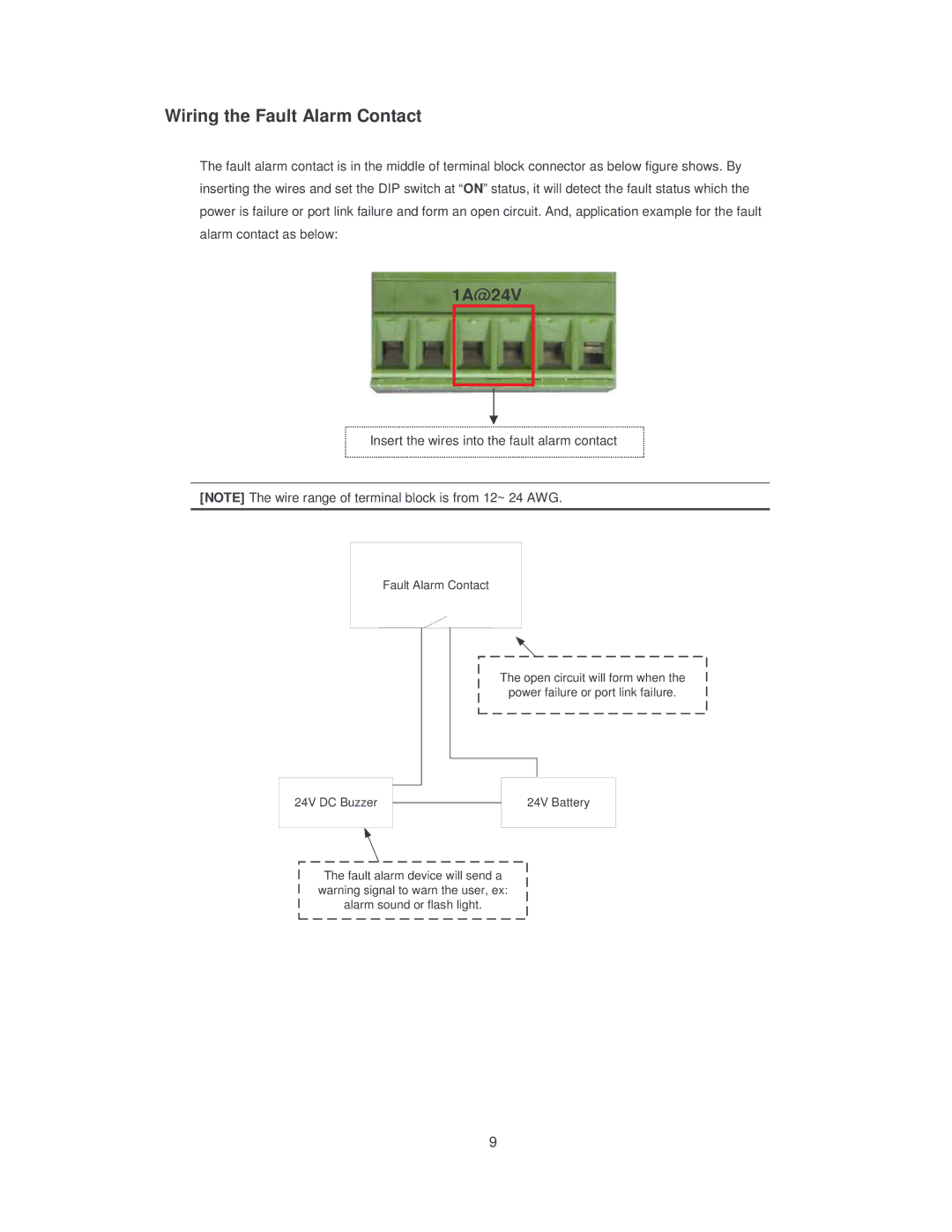
The fault alarm contact is in the middle of terminal block connector as below figure shows. By inserting the wires and set the DIP switch at “ON” status, it will detect the fault status which the power is failure or port link failure and form an open circuit. And, application example for the fault alarm contact as below:
1A@24V
Insert the wires into the fault alarm contact
[NOTE] The wire range of terminal block is from 12~ 24 AWG.
Fault Alarm Contact
The open circuit will form when the power failure or port link failure.
24V DC Buzzer |
|
| 24V Battery |
|
| ||
|
| ||
|
|
|
|
The fault alarm device will send a warning signal to warn the user, ex: alarm sound or flash light.
9