II. RECEIPT INSPECTION | III. INSTALLATION (continued) |
All Traulsen products are factory tested for performance and are free from defects when shipped. The utmost care has been taken in crating this product to protect against damage in transit. All interior fittings have been carefully secured and the legs or casters are boxed and strapped inside to prevent damage. Door keys will be attached to the handle with a nylon strip. The handle is protected by an easily removable nylon netting.
You should carefully inspect your Traulsen unit for dam- age during delivery. If damage is detected, you should save all the crating materials and make note on the carrier’s Bill Of Lading describing this. A freight claim should be filed immediately. If damage is subsequently noted during or immediately after installation, contact the respective carrier and file a freight claim. Under no condition may a damaged unit be returned to Traulsen without first obtaining written permission (return autho- rization).
III. INSTALLATION
III.d - INSTALLING LEGS OR CASTERS (cont’d): box(es), it should contain either four (4) legs or casters (RBC50 x 8 or RBC100 x 4 and four bolts for each caster).
WARNING: THE CABINET MUST BE BLOCKED AND STABLE BEFORE INSTALLING LEGS OR CASTERS.
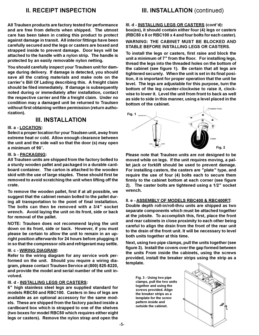
To install the legs or casters, first raise and block the unit a minimum of 7” from the floor. For installing legs, thread the legs into the threaded holes on the bottom of the cabinet (see figure 1). Be certain that all legs are tightened securely. When the unit is set in its final posi- tion, it is important for proper operation that the unit be level. The legs are adjustable for this purpose, turn the bottom of the leg
Fig. 1
III.a - LOCATION:
Select a proper location for your Traulsen unit, away from extreme heat or cold. Allow enough clearance between the unit and the side wall so that the door (s) may open a minimum of 90°.
III.b - PACKAGING:
All Traulsen units are shipped from the factory bolted to a sturdy wooden pallet and packaged in a durable card- board container. The carton is attached to the wooden skid with the use of large staples. These should first be removed to avoid scratching the unit when lifting off the crate.
To remove the wooden pallet, first if at all possible, we suggest that the cabinet remain bolted to the pallet dur- ing all transportation to the point of final installation. The bolts can then be removed with a 3/4” socket wrench. Avoid laying the unit on its front, side or back for removal of the pallet.
NOTE: Traulsen does not recommend laying the unit down on its front, side or back. However, if you must please be certain to allow the unit to remain in an up- right position afterwards for 24 hours before plugging it in so that the compressor oils and refrigerant may settle.
III.c - WIRING DIAGRAM:
Refer to the wiring diagram for any service work per- formed on the unit. Should you require a wiring dia- gram, please contact Traulsen Service at (800)
III.d - INSTALLING LEGS OR CASTERS:
6” high stainless steel legs are supplied standard for models RBC50 and RBC100. Casters in lieu of legs are available as an optional accessory for the same mod- els. These are shipped from the factory packed inside a cardboard box which is strapped to one of the shelves (two boxes for model RBC50 which requires either eight legs or casters). Remove the nylon strap and open the
Fig. 2
Please note that Traulsen units are not designed to be moved while on legs. If the unit requires moving, a pal- let jack or forklift should be used to prevent damage. For installing casters, the casters are “plate” type, and require the use of four (4) bolts each to secure them firmly to the cabinet bottom at each corner (see figure 2). The caster bolts are tightened using a 1/2” socket wrench.
II.e - ASSEMBLY OF MODELS RBC400 & RBC400RT:
Double depth
Next, using two pipe clamps, pull the units together (see figure 3). Install the covers over the gap formed between the units From inside the cabinets, using the screws provided, install the breaker strips using the strip as a template.