III. INSTALLATION (continued)

III.i - CONDENSATE REMOVAL:

All Traulsen Blast Chill models (except model RBC50) require the use of a floor drain or floor mounted electric condensate evaporator.

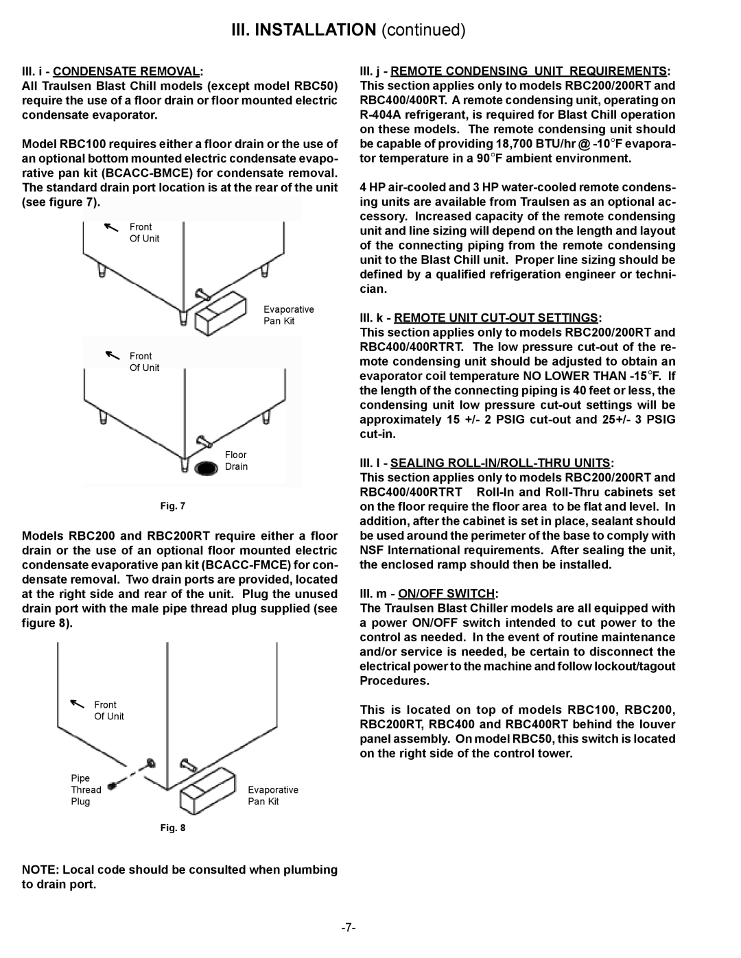
Model RBC100 requires either a floor drain or the use of an optional bottom mounted electric condensate evapo- rative pan kit (BCACC-BMCE) for condensate removal. The standard drain port location is at the rear of the unit (see figure 7).

Front


Of Unit

Evaporative

Pan Kit

Front


Of Unit

Floor

Drain

Fig. 7

Models RBC200 and RBC200RT require either a floor drain or the use of an optional floor mounted electric condensate evaporative pan kit (BCACC-FMCE) for con- densate removal. Two drain ports are provided, located at the right side and rear of the unit. Plug the unused drain port with the male pipe thread plug supplied (see figure 8).

Front


Of Unit

Pipe


Thread

Evaporative

Plug

Pan Kit


Fig. 8

III.j - REMOTE CONDENSING UNIT REQUIREMENTS: This section applies only to models RBC200/200RT and RBC400/400RT. A remote condensing unit, operating on R-404A refrigerant, is required for Blast Chill operation on these models. The remote condensing unit should be capable of providing 18,700 BTU/hr @ -10°F evapora- tor temperature in a 90°F ambient environment.

4 HP air-cooled and 3 HP water-cooled remote condens- ing units are available from Traulsen as an optional ac- cessory. Increased capacity of the remote condensing unit and line sizing will depend on the length and layout of the connecting piping from the remote condensing unit to the Blast Chill unit. Proper line sizing should be defined by a qualified refrigeration engineer or techni- cian.

III.k - REMOTE UNIT CUT-OUT SETTINGS:

This section applies only to models RBC200/200RT and RBC400/400RTRT. The low pressure cut-out of the re- mote condensing unit should be adjusted to obtain an evaporator coil temperature NO LOWER THAN -15°F. If the length of the connecting piping is 40 feet or less, the condensing unit low pressure cut-out settings will be approximately 15 +/- 2 PSIG cut-out and 25+/- 3 PSIG cut-in.

III.l - SEALING ROLL-IN/ROLL-THRU UNITS:

This section applies only to models RBC200/200RT and RBC400/400RTRT Roll-In and Roll-Thru cabinets set on the floor require the floor area to be flat and level. In addition, after the cabinet is set in place, sealant should be used around the perimeter of the base to comply with NSF International requirements. After sealing the unit, the enclosed ramp should then be installed.

III.m - ON/OFF SWITCH:

The Traulsen Blast Chiller models are all equipped with a power ON/OFF switch intended to cut power to the control as needed. In the event of routine maintenance and/or service is needed, be certain to disconnect the electrical power to the machine and follow lockout/tagout Procedures.

This is located on top of models RBC100, RBC200, RBC200RT, RBC400 and RBC400RT behind the louver panel assembly. On model RBC50, this switch is located on the right side of the control tower.

NOTE: Local code should be consulted when plumbing to drain port.
-7-

Page 8
Image 8
Traulsen RBC400RT, RBC200RT owner manual Front